- Home
- Product Categories
- Development Tools
- Touch Shield

Touch Shield
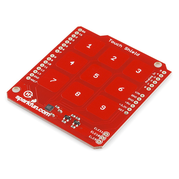
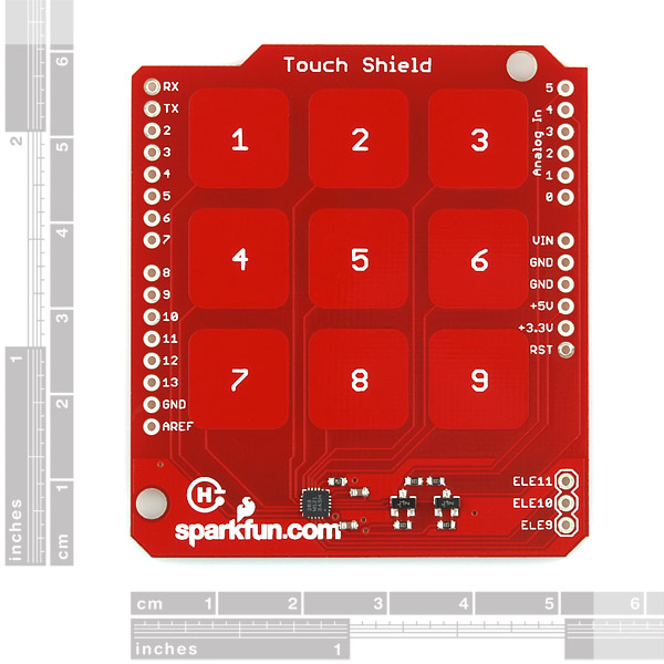
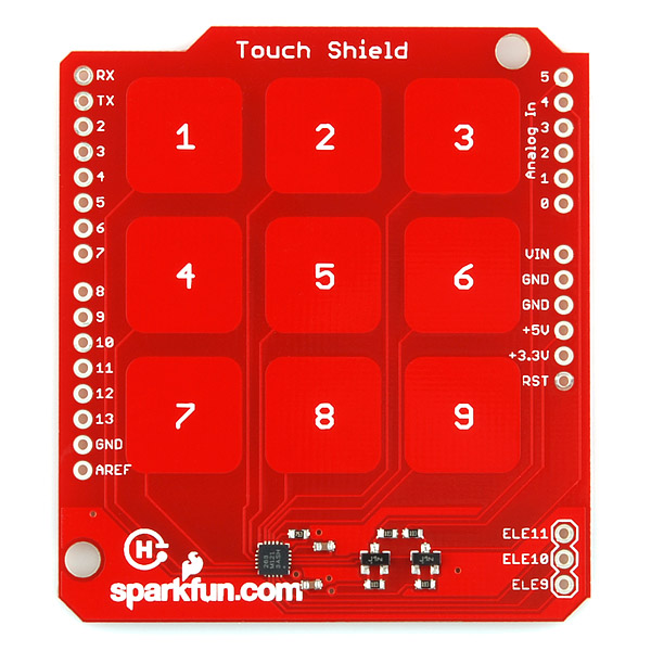
The MPR121 IC is a great way to build simple capacitive touch interfaces, and now it's even easier to incorporate into your Arduino projects with the touch shield. The touch shield has 9 capacitive touch pads, with headers for the remaining 3 electrode connections. With this shield you can have a total of 12 touch sensitive buttons. An on-board logic level converter allows it to work with 5V and 3.3V Arduino boards. Simply solder on some header pins and stack it on to your Arduino for a convenient input device. Check below for some example code to get you started.
- Schematic
- Eagle Files
- Datasheet (MPR121QR)
- Hookup Guide
- Example Code
Touch Shield Product Help and Resources
Core Skill: Soldering
This skill defines how difficult the soldering is on a particular product. It might be a couple simple solder joints, or require special reflow tools.
Skill Level: Noob - Some basic soldering is required, but it is limited to a just a few pins, basic through-hole soldering, and couple (if any) polarized components. A basic soldering iron is all you should need.
See all skill levels
Core Skill: Programming
If a board needs code or communicates somehow, you're going to need to know how to program or interface with it. The programming skill is all about communication and code.
Skill Level: Competent - The toolchain for programming is a bit more complex and will examples may not be explicitly provided for you. You will be required to have a fundamental knowledge of programming and be required to provide your own code. You may need to modify existing libraries or code to work with your specific hardware. Sensor and hardware interfaces will be SPI or I2C.
See all skill levels
Core Skill: Electrical Prototyping
If it requires power, you need to know how much, what all the pins do, and how to hook it up. You may need to reference datasheets, schematics, and know the ins and outs of electronics.
Skill Level: Rookie - You may be required to know a bit more about the component, such as orientation, or how to hook it up, in addition to power requirements. You will need to understand polarized components.
See all skill levels
Comments
Looking for answers to technical questions?
We welcome your comments and suggestions below. However, if you are looking for solutions to technical questions please see our Technical Assistance page.
Customer Reviews
No reviews yet.
Somewhat problematic without a '0'. Of course there's been a long philosophical debate about whether '0' is a number or not. I can see which side of the debate your numeric keypad comes down on! See
http://en.wikipedia.org/wiki/0_number
for further pedantic '0' trivia...
No problem if you do everything in octal. Then you can use 8 for zero and 9 for enter!
Check the friday video, you have the 3 missing keypad on some headers.
can someone help me. I've tried to run the example code but got no response when i pressed a key on the shield. Also, if this communicates via I2C how come there are no pin outs to connect the shield to the SDA and SCL lines on the Arduino?
It's connected to pins A4 and A5, which are the I2C lines. Make sure you have good, tight connections with your headers, no solder jumpers any where, and if you're still having trouble, contact techsupport@sparkfun.
It should be noted that the Arduino board used with this shield needs to supply 3.3V ! If you use it with a 5V 16Mhz Pro board it will be powering the MPR121 IC at 5V since what would be the 3.3V pin is tied to 5V instead! The MPR121 IC gets VERY hot. I don't know if mine is permanently damaged or not.
Ouch. Hopefully it's fine, but you're right that care should be taken when using this shield with any 3rd party boards that do not separate out a 5V and 3.3V pin - which includes SparkFun's Arduino Pro board.
( I would just clip the extra VCC that would have been a 3.3V pin on the Arduino Pro to prevent this completely. )
Hello, what dimensions have the PCB?
Check the Eagle files we have posted above. You can see the measurements of all the components on the shield in there. If you don't have Eagle, you can download a freeware version here.
I'm new to this, but the example isn't working, I get the error unexpected char: 'i' when I try to run it in processing.
Also, the MPR121 IC gets really hot.. what am I doing wrong here?
where can i get the "0" from then as i need as numbers
When you connect one of three external touch sensors to it, call it '0' :-D.
If seperating from the Arduino and using cables to connect, which points are most crucial to tie to the main processor?
I did not buy this, but looking at the schematic I would say GND, 3.3V, 5V, A4, A5, and D2
why dont show the correct OSHW logo..???
I think that PCB production was simply done before the "Official logo" was out. I remember that the logo you see on the PCB was the one Sparkfun selected before it got "official". They posted on February 11, 2011.
http://www.sparkfun.com/news/550
On April 18, 2011, the new logo got official:
http://www.sparkfun.com/news/592
does it work throw a window ?
I was wondering that too. Freescale's appnote AN3747 says that with large (finger-sized) pads, it should work through a 3mm dielectric. I just measured a couple pieces of window glass I had handy and they were 2.0 and 4.0 mm thick, so I guess the answer is, maybe?