- Home
- Product Categories
- Development Tools
- Ethernet Pro

Ethernet Pro
Replacement: None. We are no longer making this board but check out the rest of our Arduino-compatible development tools! This page is for reference only.
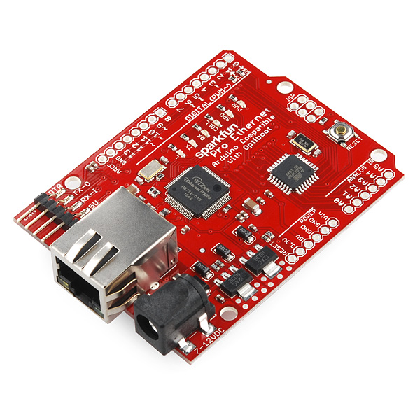
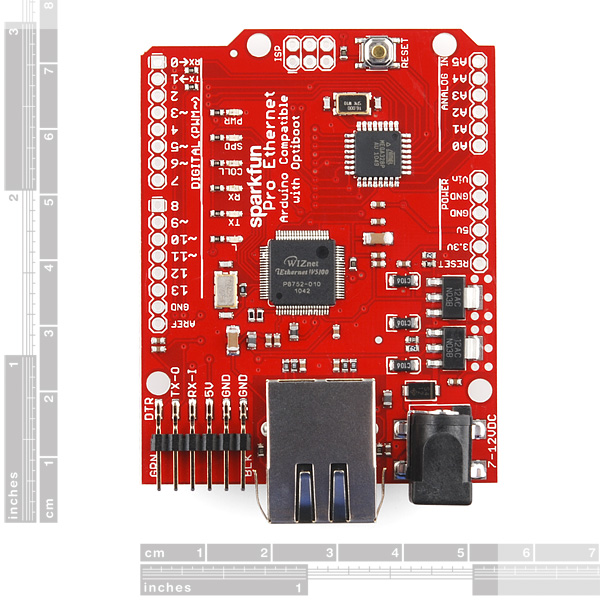
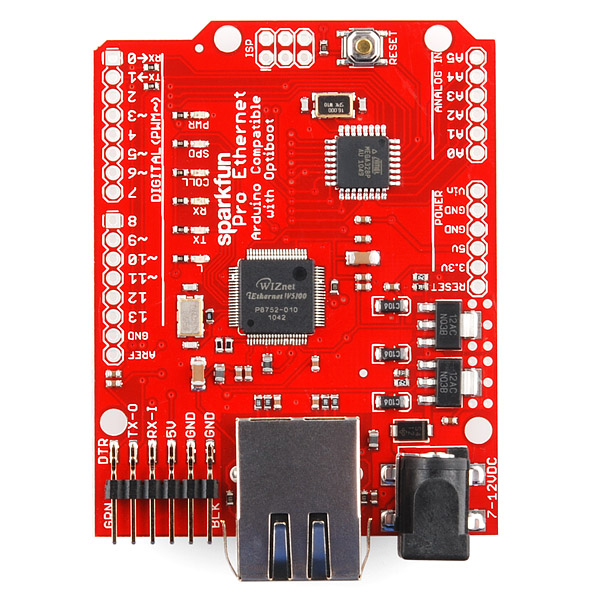
Ever wonder what would happen if you stacked an Ethernet shield on an Arduino Pro microcontroller and ran over it with a steam roller? Well, it would probably just break. But in a cartoon world it might turn into the Ethernet Pro! The Ethernet Pro is an Arduino-sized, shield-compatible microcontroller with all of the functionality of the Ethernet shield built right in!
The Ethernet Pro is based on the same hardware as the Ethernet shield (Wiznet W5100) in the same configuration so it is a drop-in replacement for the "Arduino/Ethernet double-stack," and works with all of the existing Ethernet shield libraries and code. This board features the 'Optiboot' bootloader, so be sure to select "Arduino Uno" in the Arduino IDE when you program it. The board can be programmed using either an FTDI Basic or the ATmega8U2 breakout (w/ USB-to-Serial firmware).
Not sure which Arduino or Arduino-compatible board is right for you? Check out our Arduino Buying Guide!
Note: The W5100 consumes a lot of power, so it's normal for it to run pretty warm. The regulator can also get pretty toasty, especially when it's dropping down higher voltages. For best operation, we recommend keeping the input voltage below 9V.
Comments
Looking for answers to technical questions?
We welcome your comments and suggestions below. However, if you are looking for solutions to technical questions please see our Technical Assistance page.
Customer Reviews
No reviews yet.
Near as I can tell this board does not have the reset controller for the W5100 chip that is included in the newer Ethernet Shields. I don't see it in the schematic, and often I have to push the reset after a cold start before everything works properly. Is anyone else seeing this behavior?
wait a minute, can we be clear about this: is SFE selling botched design board? If yes we should let them know to fix it and include the reset controller on the next batch...
That would explain my issues as well.. Trouble is my project is in an enclosure so reset button is nicely out of reach.
Do you know of any nifty work-arounds in hardware for this?
I did find a solution, yes.
Part: MCP120-485DI/TO-ND
Attached like so.... https://plus.google.com/u/0/photos/109341598893425115928/albums/5696781018956402065
Its a voltage supervisor, and it holds the reset pin low until the measured voltage reaches the expected voltage. (just under 5v in this case.)
im also noticing board does not always reset after programming.
@leland i would like to try your hack. but the picture link is broken.
I'm noticing that the pic is broken too.
But if I recall he basically had just soldered that DigiKey part on the bottom of the board to the three pins next to the Reset pin. (5V, GND and RST.) Prolly isn't too hard to figure out. Datasheet should pretty much give it away.
Sorry, I changed the rights on the album that photo was in... Here it is again..
Pic
honestly other than the orientation of the part, there is little more to see than my mediocre soldering skills. :)
It would be fantastic if you could add POE (Power-Over-Ethernet) support!
I plan to use several of these for a home-automation network, but I don't want to put a power supply everywhere I use one of these. For now, I'll just use split off a spare pair from my Cat5 run to distribute power, but POE would be just perfect.
I dont think its that simple. Dont you need a special POE router (source) as well and then a way to consume the power as Im guessing the power would be high voltage and would have to be transformed down. Or am I just making it more complicated then it seems?
Real (fully compliant) PoE is fairly complicated. But there is a common non-compliant "passive" implementation that works well for 10/100 installations. It just uses the two unused pairs to provide low voltage DC (in the neighborhood of 12V). You can then use "splitters" to inject power to an ethernet line without needing a real PoE router.
You would then do the same type of splitting at the Ethernet Pro end of the cable, but it would be nice if there was a jumper to just extract power from the unused pairs directly from the RJ45 jack. Unfortunately, the MagJack seems to ground these unused contacts rather than break them out for other purposes, so it would also require a new type of RJ45 jack (or I would just mod it myself).
The Wikipedia page on PoE does a pretty good job of outlining the various strategies for sending power over Ethernet. Look under "Non-standard Implementations" for "Passive" - this is what I plan to use for my setup.
If it's POE, passive or otherwise, I'd expect something like 48V, not 12V, but if you're just talking about power transfer over a pair, then sure, but it's not "PoE" at that point.
If the cable run is a significant distance, the lower voltage will lose power to a greater degree. But if we're just running a dinky little ardu-gizmo, probably not a real issue.
Now SFE is offering a passive power splitter set that will work with this board (look for CAB-10759)
POE Compatible one - http://www.freetronics.com/products/etherten
both the fully compliant PoE as well as splitters (just have to switch a tiny daughterboard on the unit, use them myself
i'd rather save the 10 bucks and grab a Passive POE Cable, my thoughts for V2 is add the passive support into the Ethernet pro. In theory fairly simple. i havn't seen the routing paths so it might be painful just my $0.02 worth.
Hey - great Link! I'll probably use a mix of these Freetronics boards (where I don't have power handy) and the SparkFun boards (where I do have power handy). Thanks
PoE would be fantastic.
This is great!
I'd also like to chime in regarding the maximum sadness I am experiencing regarding the retirement of this board! :(
Just wanted to add my voice to the people who are perplexed at this product being discontinued! I'm in the middle of a project that requires a lot of these units. The arduino+ethernet shield is a bit clumsy compared to this, as well as requiring a lot more space. I was about to place another order for quite a lot of these, and found it's no longer available.
Anyone know of a drop-in replacement, or when a successor will be available? I'm on a schedule, and need to use something in its place...
One of the main reasons we discontinued this board was because Arduino came out with an official board that does the same thing. We hit a small snag in getting our shipment so there was a longer delay between us retiring this board and getting the new ones in, but we do have them currently available. https://www.sparkfun.com/products/11229?
For anyone considering buying one of these second hand, or old stock, there is a design flaw in these boards that prevents the ethernet controller from resetting correctly. This problem doesn't seem to occur on all boards, and then on some more frequently than others. I found from the 40 boards I had, around 40% of then would fail to power up correctly, with 5 of them always requiring a manual reset (pressing the reset button) upon power on. There is a fix for it, involving some soldering, but you cannot trust these to work in a project box without modification!
As mentioned elsewhere, the voltage regulators also get extremely hot if the unit is supplied with 9v or more.
I would suggest buying the official Arduino Ethernet board instead - I've had no problems at all with those units.
This was a really great product, too bad it's retired! :-(
Is there a replacement product available? (Or one planned?)
Why did you discontinue it? Are you planning on replacing this product in the near future? I'm in the middle of designing a Computer room Environmental Monitoring solution with this the heart and soul of it.
We've got a replacement coming, and I agree - this is a really useful board.
Retired? Why is it retired? I was just about to buy a handful of these! I'd check out the other Arduino development tools, except that none of them resemble this product at all. Will you be selling the Arduino Ethernet soon? (I'd still prefer this product; I hate those stupid sockets.)
We've got a replacement product coming soon, sorry for the delay.
Why retire it? It's a great board!
Yes. Would also like to know this. We where using these on several projects.
When will these be available again?
Hello, How much power does the board consume? I've problem running it with different PSUs.
So, after looking at the schematics, looks as if you can run this off external 5v and 3.3v regulators by supplying the pins on the bd.
Anyone ever do this? Safe? Or just do external the 5v and let the 3.3v do it's job?
might be worthy to mention, you cant use several i/o pins with the Ethernet chip enabled.
from the Ethernet shield page
"Arduino communicates with both the W5100 and SD card using the SPI bus (through the ICSP header). This is on digital pins 11, 12, and 13 on the Duemilanove and pins 50, 51, and 52 on the Mega. On both boards, pin 10 is used to select the W5100 and pin 4 for the SD card. These pins cannot be used for general i/o. On the Mega, the hardware SS pin, 53, is not used to select either the W5100 or the SD card, but it must be kept as an output or the SPI interface won't work."
If I were to frankensteinianly connect a normal 9V battery to a barrel jack, could I use it to power this?
Thanks!
You could just use a 9v to barrel jack adapter to connect a battery to this (though I love the word frankensteinianly!), but again, we recommend running this with a power supply below 9v for optimal functionality.
Hi all, I wanted to get the Ethernet shield for my UNO but I found this and want to get it. But can anyone please give me the link to a programmer(from sparkfun of course) that works with this, I'm still a little confused at to which one to use.
THANK YOU
If you are getting the EthernetPro it is functionally the same as and Arduino mainboard + ethernet shield. For downloading and working with Arduino programs all you need to get is an "FTDI Basic" - it comes in 2 voltages - you get the one for same voltage as the target board - check the specs on your UNO, or if you get this EthernetPro, it is a 5V board. You use a USB cable to the USB-5pinMini on the FTDI Basic which slips onto the 6pin header on these boards and allows you to communicate/download programs developed with the Arduino programming environment (http://arduino.cc/en/Main/Software). The FTDI Basic can be removed and used on other boards of the Arduino family as needed to program or to get messages from the Serial.print functions in your Arduino program.
If you want to really totally reprogram the chip including changing or eliminating the bootloader you will need to get some other programmer for the ICSP interface.
can you stack a WiFi board on top/bottom ?
Thank you
Very good idea for a product by the way
Randy
This board is great, but the poor little ATmega328 chip soon gets full. By the time you've put in DHCP, NTP, and a web-server there's not a lot of space left - either in flash or ram. An ATmega2560-based Ethernet Pro, with a built-in uSD slot, would be tremendous.
Loving my Ethernet Pro!
One (more) question... Am I missing something? Schematic makes me think that on digital line 13 there is an LED, tied through a resistor to ground... Green, marked "L", just above the W5100?
But I couldn't get a "clean" 0v or 5v on D13's connector, and the LED never glows brightly. Usually a faint glow. Sometimes dark. Usually about 1 volt.
No, I haven't done anything nasty, like configuring it as an output, setting it high, shorting it to ground. Yes, I've tried a "blinky" program... I can "work" the another pin okay, but when I change just the pin number assignment in the program, pin 13 doesn't "behave". (I didn't have an LED on the other pin, just my voltmeter... but several LEDs are shining very brightly, elsewhere on the board.)
Is line 13 connected to anything except the LED and resistor? I believe line 13 goes high briefly on board reset (built into OS), but is there anything else going on in the Ethernet Pro, on line 13?
Speaking of lines... am I right in thinking only lines 9-12 are used for the interface to the ethernet part of the board. All other lines "free", for user's use?
I've put a small server into my Ethernet Pro... not a WEB server... something simpler. Details at...
http://sheepdogguides.com/arduino/art5simpsrv.htm
Enjoy!... I hope you will find the ideas there useful.
Regarding the LED on 13: Duh!! I think I forgot that a "pinMode(13,OUTPUT) would be needed to make the LED go properly "on" or "off". (Before I remembered that, I looked closely at the board... it does seem that JUST the LED, and its resistor, are on pin 13. (My Ethernet Pro is not tied up with "a job", or I'd go off and test whether I forgot the pinMode statement.)
I would love to see a footprint on the next revision of this board for a MAC address EEPROM so that you don't have to make one up. Something like this would be ideal, only takes one IO and it wouldn't have to be populated, the user could add it if they wanted.
Mine works, but gets extremely (as in burn your fingers) hot at the edge where the voltage regulators are. I'm using a 12VDC walwart. Could there be something amiss on my board or have others noticed the same?
I have an Arduino Decimila and I recently bought a Ethernet pro but i don't have any programmer to program the Ethernet pro. Is there anyway that i could use the FTDI chip from the decimila to program my ethernet pro?
The "BUB" from ModernDevice... oops... or the Sparkfun equivalent!!!... cost next to nothing, compared to the doors they open. You can, once you have one, have multiple Arduinos without paying for multiple FTDI chips... which you will typically only use when programming the Arduino, and don't need once the Arduino has been put "in service" in whatever you wanted it to do. In other words, it rapidly pays for itself. Sparkfun's 5v i/f: DEV-09716 $15... but get the 3v3 version, if that's what you need. (ModernDevice's BUB has a jumper to switch between the two voltage choices.)
I've modified the Optiboot bootloader to support loading programs over TCP/IP. This is very useful if you need to reprogram a board remotely.
My modified Optiboot still supports "normal" serial reprogramming, and the bootloader is still under 1KB in size.
Details and download link are on my web site.
Note that you need an AVR ISP programmer to reflash the bootloader. A cheap parallel port device is suitable.
This. Is. Awesome! Works great.
Thanks for posting!
Pleased someone else finds it useful too.
In addition to the 1KB version I have now also published a 2KB version that is much faster than RS232 (1.43 seconds to program and verify 15KB program versus 3.76 seconds over RS232). The latest 1KB version is now a little faster than RS232 at 3.02 seconds.
I still recommend the 1KB version, but if you're a speed freak and prepared to give up another 1KB the option is there.
PS: Great board, thanks!
So how does one program this? What hardware and software do I need? I am new to this..so please kindly advise..
Also in the picture I do not see the ATmega328...is it there? or what MCU is it using?
It has the Arduino Optiboot bootloader. So you'll need Arduino and either a ATMega8U2 or a FTDI Basic or Cable.
Hi Pearce thank you for replying.
Since I am new to this I had couple more questions..I hope you can help me out.
1. If I understand it correctly, the serial pin of the FTDI Basic connects to the FTDI pin on the Ethernet Pro board, correct?
2. I looked up the doc for W5100, which is essentially an MCU with TCP/IP feature. So I do not understand why do I need an Arduino for. Can you please explain? Also if I do need an Arduino where and what does it connect to? I am confused here...
3. Where do I purchase the Optiboot from since I can't seem to find it on Sparkfun?
Thanks again in advance!
hi
i just received it and i m quite surprise :
is that normal, with power from usb or with regular adaptator (fix to 9V) chips are getting really hot...
...short cut ?
You may have a solder jumper somewhere. Email techsupport@sparkfun.com. Things getting isn't normal.
1 Left!! Grab it quickly! This thing is great. Kinda more convenient than an Arduino Ethernet shield stack, and works fine doing other Arduino stuff, regardless of the additional hardware. 9/10. Only thing is the SD issue.
This is an Arduino plus ethernet, Poe, Sd card
No usb for programming
http://www.coolcomponents.co.uk/catalog/product_info.php?products_id=760
Is there any particular reason why this wouldn't work with a crossover cable and no router/switch? Just thought I would double check. Also will the ethernet jack get in the way of stacking an SM5100b shield ontop of this?
Got mine yesterday! This appears to be pre-loaded with a test program of some kind? I'd love to understand what it can do out-of-the box. Partly because I CANNOT PROGRAM IT!
I'm having the same trouble as this user: http://arduino.cc/forum/index.php/topic,66261.0.html
There is an uploading error: "avrdude: stk500_recv(): programmer is not responding"
See that forum link for more detail.
Hi Steve - did you have any luck sorting this out? Im having the same problem - using FTDI cable to connect to Ethernet Pro but Arduino (0022) on Mac OSX cannot upload sketches to the board. Board looks good (power lights, ethernet lights when plugged in) the green LED on pin 13 ('L') glows continuously at a low level... Anyone got any ideas??
I just got it working this morning. Downloaded the new Arduino IDE v1.0, selected the "Arduino Uno" board type, and loaded something. Works! A Sparkfun tech also Emailed their 'test sketch' which is very likely on your board if you never successfully programmed it. (Email me if you'd like a copy) By default, it wants to pull up as 192.168.1.177 looking for a Gateway of 192.168.0.1 I pinged that address, and it replied. The sketch will display a diagnostic HTML web page if you point your browser to it's IP address, telling you the high-low state of all the board's digital pins, and the analog values on each of the analog pins. A nice demo. Now that the Ethernet library can do DHCP, my recommendation is for Sparkfun to rewrite their sketch and provide all new units with a demo pre-loaded, and to provide the sketch as a demo right on this page. We'll see if they do!
Hi, can you send me the test sketch? Would be great! My email is: mail at pszy dot de. Thank you!
Providing an "out of the box" demo is difficult because you have to know what MAC addresses and IP addresses are not yet in use on the LAN the Ethernet Pro is going to be plugged into.
Yes... it would be possible to send them out with known MAC/ IP addresses, and advice to the customer to unplug anything already using those before trying the Ethernet Pro out of box demo.
But the customer who understands that, can probably load the test program of his/ her choice anyway.
this is great! whats the power input? same as the arduinos i assume, can it take 12vdc?
Looks like it has breakouts for ISP programming, but that's not mentioned in the product description. ?
How easy is this to hook sensors up to, and have it "tweet" the data? Bare in mind I've NEVER used an arduino before, though I do have some experience using micro-controllers.
It shouldn't be too hard, since there are tons of example sketches online.
Oh that's excellent, thank you :D
I wasn't sure if I needed specific hardware, or whether it was all hardware driven.
What's the power requirement for the DC input? I figured it was like the Uno that could run at 5V but liked to have a bit higher voltage, but it really didn't like the 8.5 volts my power supply was providing. The voltage regulators got pretty hot and the board would switch on and off regularly.
The silkscreen says 7-12VDC but so far I've only seen it work properly with a 5VDC input. That's pretty disappointing considering I'd planned on using the 12V inverter and EL escudo in conjunction with this board.
I'm having the same problem running it with a 9V wall adapter. Voltage regulators get really hot really fast and so does the Wiznet chip. Had this problem prior to hooking the board up to anything. I am reading 5V output and 3.3V output for as long as I dare to keep the 9V adapter plugged into it.
Great idea, but unfortunately the ethernet jack interferes with stacking other boards (in my case, the el escudo) using the standard "stacking headers" offered here.
I suppose you could stick nylon washers or something like that between the board and the headers to offset them enough, or you could put the headers on the opposite side of the board (provided you're smart enough to make sure the stacked boards also are reversed).
It would be easy enough to create an "empty" shield, with a cut-out to allow for the Ethernet connector. Then the stack would be....
Whatever shield you wanted
The "empty" shield
The Ethernet Pro
Is this true? I want to stack the SM5100B shield ontop of this one is it not going to fit? any views/experience?
That is too bad as it should be possible. The Netduino Plus has a low profile plastic ethernet jack that allows shields to mount normally.
So is there going to be a WiFly equivalent of this (kinda like the BlackWidow)?
Does this autoreset like a standard arduino whenever you open or close a connection, or can that 'functionality' be switched off (other than by the resistor trick) ?
I'd love to see a you-tube video of this device in action. The possibilities are so open I want to see what people do with it.
There's tons of youtube videos of the arduino ethernet shield (it's one of the most popular shields available) and this does the exact same thing, just for a lower price.
Since it is a version of the arduino pro you guys should also have the jst plug in so we can also hook it up using li-poly batteries
I love this. Actually bought 2 last friday. But im trying to work out how many of the Digital pins are used for the ethernet part, and how many are left for me to do stuff with.
Is it right that digital pin 0-11 and analog 0-5 is open for fun?
Good question. The ATmega328 default SPI pins are connected to the ethernet chip, that is digital 11-13. Digital 10 is used as the chip select.
Also, optionally, digital 2 is tied to the INT pin of the ethernet chip, using the jumper on the bottom of the board. By default though, that jumper is left open. All the rest of the pins are open.
All the other pins are open for all they fun they can have!
Does this mean I could use SparkFun Xbee shield with it? I don't think XBee shield uses any of these pins except pin 2. Am I correct?
Hum freetronics has one like this but it has the sd card slot usb on board and its also 12v PoE (not standard 48v) might want to check it out.
It's also $15 more expensive...
As far as I can tell Sparkfun did not set out to build a clone of the Etherten.
Freetronics also offer the EtherTen without the PoE module, for less... but still more than a Ethernet Pro.
Why this talk of "cloning"? Such an obvious product was bound to be produced by more than one supplier, surely? I for one am glad of the chance to choose an supplier, and to feel confident that if either one stops selling their Arduino-with-ethernet, there will still be one available for any apps created for it.
I'm new with arduino and i would like to start with this development board, but i have a question. wich FTID is recomended the FTDI Basic Breakout - 5V or 3.3V? The 3.3 V version is listed on related products but is the recomended version?
I know this is a delayed response, but use the 5v FTDI.
Seeing as the Ethernet Pro is described as "Ethernet shield on an Arduino Pro", and that 5v and 3v3 versions of the Arduino Pro are sold by Sparkfun, and the, I would assume, dire consequences of attaching 5v to a 3v3 device, I would have thought that the question above would have prompted a clarification in the "official" product description. I don't know if I'm on the road to disaster, but I have an Ethernet Pro that arrived today, and I am programming it with a ModernDevice "BUB", with a wire link in place (necessary, to whatever voltage is right for the Arduino being programmed, for devices with Optiboot) by the way) selecting 5v... and my system is working so far... but haven't been using it long. The regulators are quite warm, the Wiznet almost hot enough to burn the back of my finger. This with BUB connected, supplying 5v, but nothing else plugged in, although a program is running, a little server... but with no LAN connection at the moment, it doesn't have any "serving" to do.
I would assume that unless otherwise stated, this arduino is a 5V one, so hence you would use a
5V FTDI.
Would it make sense to turn the top view picture 90 degrees so we could read the silkscreen better?
Nice product! I have just started using the similar EtherTen board from Freetronics - http://www.freetronics.com/products/etherten which does have USB and POE. It would be interesting to see a comparison.
3 days ago i would have bought a box of these
You can still buy half a box now ;-)
I've been there man!
It's not accurate to call this "a drop-in replacement for the "Arduino/Ethernet double-stack", since the Arduino EthernetShield includes an SD card slot.
Still, thanks for the hard work creating more Arduino options.
So, is this more like an Arduino Pro with Ethernet or Arduino UNO with Ethernet minus USB? I noticed that you have 5V and 3.3V connections while you can power up to 12V. I think on the Pro, if you put in 9V to Vin, you would get 9V at the normal pin locations for 5V and 3.3V.
To me, it sounds more like an UNO where you have to use an FTDI instead of USB cable.
Except for the added fact that u have a WizNet W5100 and The big hole on the side to put an Ethernet cable...
But other than that ur right! lol thats kinda the point of an arduino pro...
Why no SD slot? It would only take a few extra components and make this vastly more useful.
We didn't have the room. Maybe next revision.
I was thinking about sticking it on the bottom of the board, but then you would have problems having it fall off when re-flowing top. If the pads were there, the user could add one later though.
Yeah, it would 'fit', but I'm not sure we would have room for all the traces. worst case, we do have the microSD shield. we'll look into it.
Have a look @ http://www.freetronics.com/products/etherten
The W5100 is a great IP stack - four concurrent sockets open. All the hard work is done by the chip - TCP, IP, ARP, ICMP, etc.
The SPI interface is a low pin count interface, and can run at 4 or 8Mbps.
Cool. Can we get one of those with the WiFly built-in next?
I'm not 100% sure, but I think we're working on something like that. It's a bit more complicated since the wi-fi modules are quite a bit bigger.
That would be sweet! I'd go for a pro+wi-fi. Perfect for a lot of projects.
Now that's really nice =)
No room for a miniUSB connector and an FTDI chip over to the left of the ethernet jack (where the 1x6 right-angle headers are), huh?
Hard to call it an Arduino stack when you can't program it with the normal Arduino hardware.
--Joe
They did not put any FTDI and USB connector to reduce price! The FTDI chip is expensive!
That's kinda why its called an arduino pro?
just like this one: http://www.sparkfun.com/products/9219
But with an Wiznet W5100 on it... makes sense?
All you need is an FTDI basic, FTDI cable, or ATMega8U2 breakout. This is the same way our Arduino Pro works.
it seems that there is a solder bridge between a few pins of the WIZnet IC (top left) in the second picture
yep, check the schematic, a few pins on that IC are tied together.
ah makes sense, thanks
With regard to people who have found the voltage regulators getting very hot on these boards, i have tested this out on one of our boards using a bench top power supply.
At 5V, the board consumes approx 180mA when not doing anything, but doesn't get hot.
When the voltage is increased to 9V the regulators get warm, but acceptable, they are not hot. Power consumption is about 200mA.
If the voltage is increased to 12V, the regulators get hot quite quickly although current stays at about 200mA.
It would seem the regulators are not up to the task at 12V. The board should really be supplied with 7-9V DC and not 12V