- Home
- Product Categories
- Sensors
- Weather Board - USB

Weather Board - USB
Replacement:DEV-12081. We've turned this board into a shield and updated quite a few things, go check out the new version! This page is for reference only.
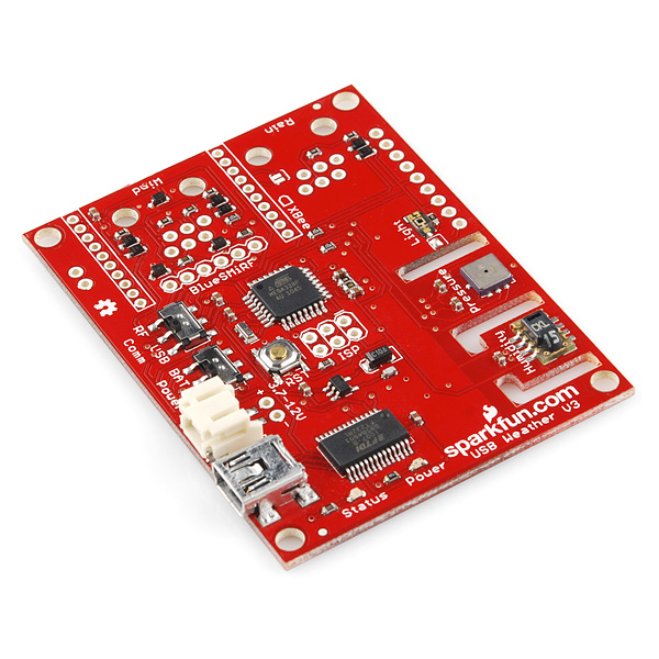
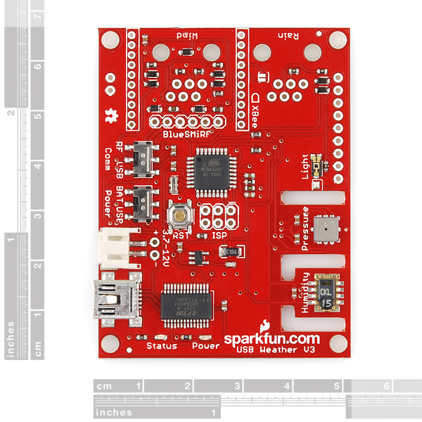
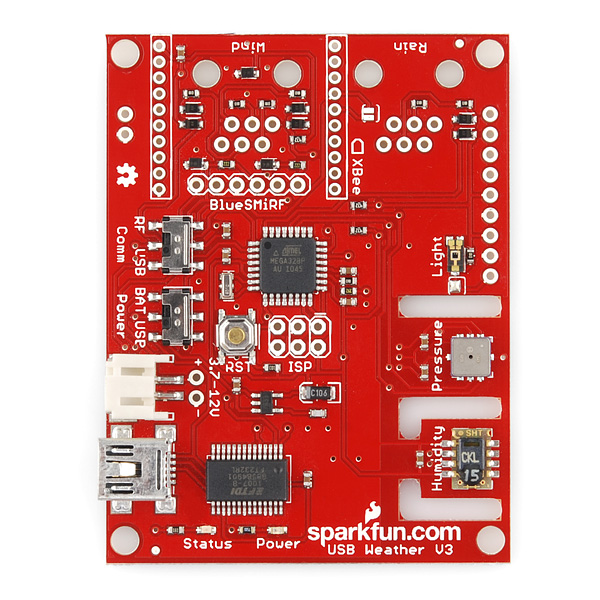
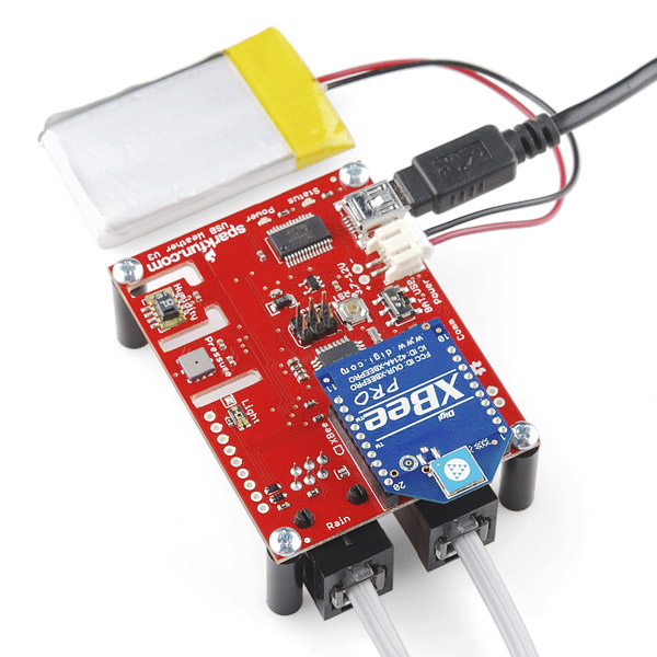
Got weather? This board can handle it. The USB Weather Board includes onboard sensors for barometric pressure, humidity, temperature, and light level. We've also added headers in the new version so you can connect the board to our weather meters (not included), adding sensors for wind speed, wind direction, and rainfall. You can send all this data to a computer or datalogger via mini-USB cable, TTL serial (3.3V), or wirelessly via Bluetooth or XBee (not included). Finally, the board is Arduino-compatible for easy customization.
This board has a wealth of headers for various sensor and communication connections. Check the related items below for the appropriate connecting hardware. Our weather meters can be connected to the weather board with the addition of RJ11connectors. Wireless communication can be achieved through either Bluetooth, by the addition of 0.1" headers and a BlueSMiRF radio, or Zigbee by addition of an XBee radio and the appropriate XBee sockets.
Replaces:SEN-09800
- Arduino compatible (3.3V 8MHz ATmega 328)
- On-board sensors for Barometric pressure, Relative humidity, Ambient light and Temperature.
- Headers to connect Weather Meters, BlueSMiRF Bluetooth modem, XBee radio (not included)
- 3.7-12VDC power can be supplied by USB, LiPo battery (JST connector), or other external source.
- Default serial output: 9600bps 8N1
- Stock firmware allows you to choose between multiple units and output formats.
- Schematic
- Eagle Files
- USB Weather Board V3 Datasheet
- Datasheet (BMP085)
- Datasheet (SHT15)
- Datasheet (TEMT6000)
- Hygrometer Reconditioning Note
- Firmware v1.1 (previous versions of Arduino IDE)
- Firmware v1.2 (Arduino v1.0)
- Firmware v1.4
Weather Board - USB Product Help and Resources
Core Skill: Soldering
This skill defines how difficult the soldering is on a particular product. It might be a couple simple solder joints, or require special reflow tools.
Skill Level: Noob - Some basic soldering is required, but it is limited to a just a few pins, basic through-hole soldering, and couple (if any) polarized components. A basic soldering iron is all you should need.
See all skill levels
Core Skill: Programming
If a board needs code or communicates somehow, you're going to need to know how to program or interface with it. The programming skill is all about communication and code.
Skill Level: Rookie - You will need a better fundamental understand of what code is, and how it works. You will be using beginner-level software and development tools like Arduino. You will be dealing directly with code, but numerous examples and libraries are available. Sensors or shields will communicate with serial or TTL.
See all skill levels
Core Skill: Electrical Prototyping
If it requires power, you need to know how much, what all the pins do, and how to hook it up. You may need to reference datasheets, schematics, and know the ins and outs of electronics.
Skill Level: Rookie - You may be required to know a bit more about the component, such as orientation, or how to hook it up, in addition to power requirements. You will need to understand polarized components.
See all skill levels
Comments
Looking for answers to technical questions?
We welcome your comments and suggestions below. However, if you are looking for solutions to technical questions please see our Technical Assistance page.
Customer Reviews
No reviews yet.
I already bought this board for my final project. Can I send the data from this board to a web server via gprs using SIM900 module?
I used the xbee s6b wifi module in my project and it worked posting to the sparkfun data server. I've never used the gprs modules but I can imagine if it hooks up similarly it will work fine. I know it's been 3 months since you asked the question but I thought I'd let you know anyway
Has anyone else seen an issue when you plug in the USB Weather Shield and you get BSOD windows 10 "Stop Code: PAGE FAULT in NONPAGED AREA". I get it one my Desktop but it works fine on my Laptop with Window 10.
I like the isolation you guys did around the humidity and pressure sensors.
I have asked Brian, of weather-display software,
http://www.weather-display.com/index.php
to add support for this board. after a week of beta testing with him, he has released a new version of the software that now supports the sparkfun usb weather board. i have used this software in the past and if you're serious about weather, this is the software to use! Go check it out and if anyone has questions on how to set it up with the sparkfun usb weather board, just ask me and ill be glad to help!
@mikerector: hai, can you help me to set the usb weather board with the software. I had installed the software but i have no idea how to play with it.thanks.
@mikerector: How did you get the WeatherDisplay software to work with the USB Weather Board? I downloaded a trial copy and haven't been able to get it to work properly. Sometimes it talks with the board (but gives erroneous readings), other times it does not even communicate with the board. I have selected the "Sparkfun" board in the Control Panel settings. Are there any other settings or procedure to follow that I need to be aware of? For that matter, what other display options are available for this weatherboard? Thanks.
i too ran into that problem i'm not sure why it does that,(it did seem that at first it wouldn't read the data but after about 3-4 min, it would read everything fine), but i found that if you shut the software down and reboot the board, wait for the board to reboot, (status led flashing at the preset data transfer interval) then start the software, it will then start receiving data. be sure to set the board to output csv data, not ansi and baud rate at 9600. it should then be working. hope this helps.
Well, turns out I was able to stumble my way into a working solution, employing essentially the same advice you've given here (setting CSV output on the USB Weather Board being the biggest problem with my setup). Everything seems to be working fine now, but I'm still not sure about how the update-rate matching works between Weather Display software and the USB Weather Board. They each have a way of setting the data refresh rate, so if even if you have the same update rates set on both of them, I wonder how it is that they actually sync? The USB board PUSHES the update, the Weather Display software PULLS it. So are there twice as many updates?
What I'd really like to do, ideally, is get a front-end set up for this using Processing or some other easy-to-program graphical application development software. Are you aware of any such projects ported to the USB Weather Board?
Thanks for the help.
hello,
i am looking to buy the SEN-10586, but after i do i will have to make this board round and create few changes, but i have few questions before i proceed:
could you please let me know if you have a downloadable parts list or BOM file? can i freely do modifications to this board?
regards Thanks
The "Eagle Files" link following the product description are files for the EAGLE schematic and PCB editor that we use. When opened in Eagle, you can extract a bill of materials and change the board and schematic all you wish. Like many of our products, this board is Open Source, so you can modify and use the design as you see fit. Good luck!
thank you for your reply.
wish me luck :P
My USB Weather Board arrived in the mail yesterday. I plugged it into an old camera USB cable and connected via Terra Term. Within minutes I was getting weather data back from the board. I really thought it would be harder to set up. Thank you Owens & Grusin for a great design! The anamometer, weather vane and rain bucket have yet to arrive, so I still have time to brush up on my soldering skills. My XBee WiFly came in the same shipment, but I'll save that comment for that product page. I'll report back when I get the two married up or when I have more questions. ;-) Great job Sparkfun!
(replying with an update) I was able to solder in the sockets for the XBee/WiFly and RJ11s without seriously damaging anything. Since I had already set up the WiFly for telnet (See my post on that product page) I just plugged in the WiFly and opened up a connection. I started seeing weather data immediately. Since everything seemed to be working, I plugged in a new freshly charged LiPo battery (PRT-00341), restarted the connection and let it run. It ran on the battery for 15hrs, 25min, 29sec. The battery voltage started at 4.13v and the last reading before it failed was 3.43v. I suspect it would have run longer with the LiPower Boost Converter (PRT-10255). I guess I'll be picking up one of those next. Doing the math (850mAHr/15.43472HR) gives an average current draw of 55.1mA. That's pretty rough guestimate at this stage. I want to experiment to nail that down better. Also, I had the transmitter set to full power. I expect I could back that off some. Anyway, still liking this product!
Hi all.
We present the new version of code:
1.1 grualia beta, 2011/08/12 http://www.grualia.com
Download in the link:
http://www.grualia.es/download/software/Weather/WeatherBoard3v11.rar
In the next version 1.2 we will allow view correctly the altimeter.
Remember update all libraries added in the compress file.
1.1
- fix errors that math formulas, sensor infinites waiting, bad logarithmic operations, communication port blockings, memory access problems,
- we change the CSV (it is NMEA really) and ANSI string. We have to do it because in the next version 1.2 release, we can to select if sensor is a BASE (to send corrections to other sensors) or MOVIL (that receive the correction). Now, we can have one MOVIL fitted correctly with one BASE. Of this way, we can have one real ALTITUDE corrected.
- more units of temperature, pressure...
(continue)
Does this have any capability of charging the battery while connected to USB or another external power source?
Nope, sorry, couldn't fit it in there! We have various chargers though.
Will you be making a revision with the charging feature?
It seems rather inconvenient to have to go to a remote Weather Station to recharge the battery every time it runs out, besides its not very good for the battery if we do leave it to run completely dry.
So then, I'd have to get a Solar Panel, a charger, the battery and then wire all that up to this.
Also It would be rather convenient if you guys included the 2 XBee headers with this, preferably as SMD parts to make it easier on soldering them on.
Can I use a Dht 11 with this board? what pins can I use?
I hate asking for help on an obsoleted product, but I have one and I would like to get it working enough to use it.
I also have the same problem with the libraries... Class SHT1x has no member connectionReset
I pulled the libraries from the distribution. Any thoughts ?
Hello, sorry for the late response. Have you solved your problem? The libraries included with the 1.4 version of the software should solve your problem (note that you need to replace older versions of the libraries with the new ones). If you're still having problems please contact our tech support department, they'll be happy to help you out.
I see that there are zero of these in stock, and there are zero planned. Is it being discontinued? I've been using v2 for a project at work, and we were hoping to buy a few of these for our next project. Unfortunately, the shield version (along with a separate Arduino board) would make things too thick for our application. Please bring them back!
This version of the Weather Board has been retired because the BMP085 pressure sensor that it relies on has been discontinued. But don't worry, we're finishing up a revision of this board that uses the newer BMP180. Unfortunately there is currently a worldwide shortage of those parts so it's taking longer than we hoped to switch over. Sorry for the inconvenience; look for the new version in late February or early March.
Hello,
I do not understand what that means "Changed sample_rate to 32-bit, max = 4294966 seconds (47 days)"
should I manually reset every 47 days the weather board v3? it's for a long time instalation
Best Regards, Sebastian
No, this means that you can set the sample rate anywhere from 0 seconds to 47 days in one second increments. If you want to sample every second, it can do that. If you want to sample once per month it can do that as well.
thanks
Just recently got the weather board. I have set the output to CSV format. I am using Coolterm as terminal program as suggested on this forum, After I reset the board, I see the word RESET. Then after a few lines of output, the terminal program does not display any data. What could be the issue. I need to capture this data into a file.
You're seeing a few lines of valid CSV data, then the board stops responding? Here are a few possibilities to check:
Ensure you're using a good power supply.
Ensure your terminal program is working as you expect (it may not be showing new data). The Weather Board will blink the green status LED each time it outputs a line of data. Does the LED continue to blink after the text stops?
If it isn't, update the Weather Board to the latest firmware available at the top of the page (pressing "CTRL-Z" to show the Menu will show the current version; the latest version is 1.4). A recent fix in the new firmware is a lock-up-after-reset issue, but that issue would not have displayed any data.
If you continue to have problems, please contact our tech support department, who will be happy to help you further and get you replacement hardware if necessary.
I want to measure how often a pump i starting and stopping. The pump is controlled by an flotation sensor.
Is it possible to measure this by the weather board (I2C?) ? I use the weather-display software and it would be nice to get the graph of how often the pump starts.
Look at this sketch: https://docs.google.com/file/d/0BzXszPb1ByPmcGdBLV9hN3UwSms/edit?usp=sharing
I appreciate if someone would help me!
** I am really interested in this product!**
Thanks.
That's hard to say, I believe the precision specs are comparable, but I'll usually see a degree difference between them. You should do your own calibration against a known source if you need absolute accuracy.
You can certainly implement everything on another Arduino, with the sensors on our breakout boards, and the code should run without modifications as long as all the sensor lines are going to the same pins (or if you modify the code to use your new pins).
Thanks for your help!
1. So could I just plug in the Humidity/Temperature Sensor and Barometric Pressure/Temperature Breakouts directly into the I2C on the Arduino?
2. I noticed that the Barometric Pressure Sensor runs at 3.3v, but what about the Humidity Sensor?
3. I noticed that there is a portion on the schematic that is dedicated to the Weather Meters (Wind and Rain). Would I have to change any of it to use it with an Arduino? (would there be voltage problems?)
4. Lastly, I am going to use a Raspberry Pi as the data logger/web server (I may end up using a faster computer for the server). Should I just use USB/Serial (Serial over USB; built into the Arduino Board) or would I2C be faster? I would have the Arduino as the master and then send the processed information to the Raspberry Pi. Would the SDA/SCL lines be slower because of the sensors on the "network?" It seems (from what I saw in the code) that the Arduino would be constantly sending data to the Raspberry Pi, not only if there is a change (I could alter this, of course). So, USB/Serial or I2C? Now that I think of it, what about SPI?
Thanks so much! I can't wait to get started on this project!
(I'll give you an inside scoop that we're going to be releasing a shield version of the weather board within the next two months. Since you're going to be duplicating a lot of it you might consider waiting. ;)
When is this version planned released? Do you have more info about this shield version?
This is Nate's baby so I can't give out any details, but we're very close to production so you should see it on the storefront within the next few weeks.
One suggestion: Omit the ambient Light Sensor. I think that most people buying this board would just the most common data (Wind, Temperature, Humidity, Pressure). I mean honestly, 12:00AM: dark; 1:00AM: dark; 5:00AM a little lighter; 8:00 AM: very bright. If you really wanted to measure it, you could either attach the breakout board separately or just use a photo resistor. Maybe there could be an "expansion port."
Just a suggestion
I notice that there is no connection to pin9 of the XBee socket. I am thinking of modding the board so I can get a signal on the Sleep pin, so I can alter the software and cut the power consumption way down. Before I do, has anyone had any experience with this? Thanks.
Is there a recommended method to mount the unit? The case would have to allow air flow for accurate temperature readings, and a way to expose the light sensor to the sun. Thanks
Look through the rest of these comments. There is a bit of discussion on that subject.
New firmware V1.4 is available. This firmware improves operation and fixes several issues.
Because the Arduino Serial Monitor does not support control characters, you can now use 'z' 'Z' or CTRL-Z to enter the menu system. The menu code has also been changed to fully support the Arduino Serial Monitor for data entry. Operation is unchanged for other terminal software.
A problem was identified and fixed for an intermittent startup lockup on some units. The SHT15 is not a true I2C sensor, but uses the I2C bus. It was found that this sensor could lock up the current implementation of Arduino's Wire library on startup. Nathan Isherwood submitted a SHT15 library patch that works around this issue. Note that you will need to replace your SHT15 library with the supplied version (see below).
An incorrect rain gauge constant was identified thanks to Michael Bauer.
Moved all constant strings to flash; there are now over 1K bytes free!
The new firmware is located on Github at: https://github.com/sparkfun/USB_Weather_Board. You can download it by clicking the "Download ZIP" button. This code was tested under Arduino versions 1.0.4 and 1.0.5. Be sure to replace your current library versions with the libraries included in the archive. Installation instructions are included in the Readme file.
Has anyone ever had any issues with one of these hanging? I have it plugged into a linux box, I connect using
screen /dev/ttyUSB0 9600. I then get a "RESET" and nothing else. It hangs and does not accept a ctrl-z.Hi Matt, funny you should ask, we just released a fix for that bug. Try out the new firmware available on Github at: https://github.com/sparkfun/USB_Weather_Board and let us know if it solves your issue.
My Mac running the Arduino IDE does not accept the control-Z command to configure the board. I don't know why, but I did find a way to configure the board with the Mac. In case anyone else has this problem, here is how I solved it. I used the TERMINAL program that comes with OSX. You will need to know the name of the port your Mac is using for the board. You can get this by running the Arduino IDE and pulling down the "Tools" menu. Look at the "Serial Port" item in that menu and the port name will appear there. When the program starts running, type this code (be careful to use the correct case for the letters and put in a space between the "screen" command and the first "/"):
screen /def/the rest of the port name you get from the Arduino IDE "Tools" menu
Press Return. The screen will go blank for an instant and then you will see the data from the board appear. Now you can enter control-Z. I had to type it a couple of times because the data is coming in so fast (the default setting is one data set each 2 seconds) that the serial port is busy handling the incoming data for a lot of the time. You have to find a gap when the port is idle so that it can "hear" your control-Z. When it does hear the command, the configuration menu appears and you can proceed exactly as described in the SparkFun data sheet.
This weather board sounds awesome. But It says it measures light intensity. What kind of light does it measure? In the weather station market this means all sorts of things. Most stations measure solar radiation in W/M2 or watts per square meter. I've also seen light measured in Lux. The Weather Bug stations at least the older ones measured light as a fraction and was expressed in the same way as humidity "%". Some stations also measure light in footcandles. I'd also like to extend the sensor away from the board. It's not too hard to remove a component with a soldering iron but how long of a cable can I extend the sensors without severally impacting the accuracy?
As for the wind sensors, Can this board be used with industrial grade anemometers such as NRG, R.M. Young, and Campbell Scientific?
This board includes a TEMT6000 light sensor, which is a phototransistor that is sensitive to visual wavelengths. The spectral response is in the datasheet which is linked at the top of this page. The stock software outputs a percentage value from this sensor, however this is simply the sensor's voltage response and is not calibrated to any real-world units. We highly encourage people to modify the board and code for their purposes; with some measurements against a calibrated instrument or station you could likely use the sensor to estimate local insolation in the units of your choice. Do note that this sensor does not have the UV and IR response of a true pyranometer, but on the plus side, it is a fraction of the cost. The board is already set up to easily accommodate a remote light sensor (see the USB Weather Board Datasheet linked above for details); I'd be comfortable extending it a foot or two without significant signal degradation.
The anemometer and wind direction sensor inputs are set up to count switch closures as used in the Weather Meters that we carry. You could likely easily adapt it to other sensors; we've provided full schematics, board layouts, and software source to encourage you to do so.
Hi, is possible to reset the board, by an external pin? for example, sending a low signal, using GPIO output from another board, to pin 5 (RST) of ISP programming header.
Yes, that should work fine.
hai, i would like to ask, is it possible if i set the sample rate=1800 seconds? and is it possible the data will be loss if i run the program 24/7?because i had lost some data when the board in connected. thank you,.
Yes, it's possible to set the sample rate to 1800 seconds. I'm not sure what your data loss issue was; the board should be cable of running 24/7. Please let us know if you continue to have problems.
ok tq, i will let u know there any problem occur..
Hi,
I am interested in use USB Weather Board SEN-10586 with LPC1769 by UART connection. Is possible to put this board in sleep mode (reconnect sending characters or other system)? Have a detailed manual for configuration and operation ?. I need more information to connect and operate ... Thanks.
Take a look at the USB Weather Board Datasheet linked above. Sleep mode is not programmed into the stock firmware, but the board is Arduino-based and very easy to write your own programs for.
Thanks for your reply. I have some more questions: is possible to retrieve information on request? ie, send a command xxx and receive response without using the function of sending readings every x time. If possible, as is done?. Regarding running time, how long it would last with a 5V battery and 2100 mAh? Would not it be better to use a solar panel with the features needed in this case? Know anyone that fits these characteristics and where to buy?.
Thank you very much for your attention, I have been very helpful !!!
hai, i just bought this usb weather board and i have problem which i not be able to connect it with the weather board. anyone willing to help me to set up this thing especially on the programming? thanks
Take a look at the USB Weather Board Datasheet which is in the links at the top of this page; if that doesn't answer your question let us know and we'll be happy to help you out.
i just recently able to see the live data. as for now, i would like to ask how i able to change the default behaviour of the board because when i sen a ctrl-z, nothing happen as i would like to change the units for temperature and wind speed.
Make sure both switches are set to "USB" before sending CTRL-Z.
yes, i had make sure both switch set to USB but still nothing happen.
What terminal program are you using?
im using hypertrm program..
You have clicked the Hyperterm window to make it active?
You are holding down the CTRL key and pressing the Z key?
You might try a different terminal program, such as Coolterm, but this should work in Hyperterm.
i tried using hyperterm but still nothing happen. n i had tried the coolterm as your suggestion and it success. thanks for your guide.
thanks for the feedback. i had read on the datasheet and i also had connect the usb board to my laptop which is success. the problem i have now is how to run it and is there any specific software should i installed in order to run the board.this is because when i connect it to my laptop, there were nothing happen..and also what does it mean by ANSI-aware terminal program?
Can any one please give the code that should be uploded to the board so it will work . Because I got it new and I am not able to programe it also I do not now how .
Hi, the Weather Board comes with code pre-installed and working, so you do not need to upload code to it UNLESS we provide an update OR you want to write your own code.
Can't make readings faster than 1 per sec approximately and also there seems to be some sort of low pass filtering on the wind speed data. Anyway of making this faster and more nervous ? Tried putting sample_rate at 0 but didn't help. Thanks anyone for your time.
A sample rate of 0 will make the board sample all the sensors as fast as possible, however this is limited by the fact that the pressure and humidity sensors take a while to complete their readings. If you don't need those sensors you could bypass them in the code and speed things up.
As far as I recall there is no low-pass filtering on the wind data except for debouncing of the rotation sensor, which is quite noisy. (There's also an upper limit on the rotation timer, which will zero the wind speed if it doesn't get a tick after four seconds). If I'm doing the math right, the current code uses 20ms of debounce per revolution, which limits the max rate to 50 revolutions per second, which is equivalent to 132 MPH. If this isn't enough for you by all means change the code (and send us pictures of what you're using it for!)
I'll add that this wind speed sensor is naturally limited in resolution by the two-ticks-per-rotation internal sampling and the inertia of the spinning portion, so it may not be able to provide the nervousness you need. You might look into another type of anemometer such as sonic or hot-wire that are more instantaneous and might be better suited for your application.
This uses a USB mini or micro plug that I have NOT used before. Can anyone tell me the cable needed from Sparkfun? It has 5-pins male in a mini USB plug??? I am connecting it to the Weather Board above.
Dennis Thanks fr the help!
That is a mini-B USB plug (they all have five pins, look at the cable end). If you're having problems getting a standard cable into it, it may just be that the new connector is tight. If you continue to have problems please contact our Tech Support department and they'll get you a replacement board.
output reading is it analog or digital ! because I am doing a project and I want to use to be samulated with labview .
Also the output reading is it just a number or its in volteges !
wating your reply
You should read through the "USB Weather Board V3 Datasheet" linked at the top of this page; it should answer all your questions.
Can you send me the code in MikroC because i dont know the formulas of finding their specific value displayed in LCD.. pls email it to donbermoy@engineer.com
We don't use MikroC, so no we can't. The firmware link above is in plain text, and was written in Arduino C, so you should be able to easily understand or port it to other systems.
Any chance of this board ever going on sale? (I have a psychological barrier about paying more than $100 for it)
We don't really do sales. If a new revision comes out (none are planned for this board) we will sometimes reduce the price on the old one to clear out the stock. Or you could try to win one of our contests or free day. But other than that, sorry. :(
Hey guys. For the 3.7V Lithium Power battery, how many ampere's does it need to run the USB weather board AND the Logomatic V2 Serial SD Datalogger? I want to make sure I know which battery to get before I start buying parts and I am out of luck on the power. Thanks!
The Weather Board will use about 15mA without a radio. Not sure about the Logomatic, I'd guess it's in the 25mA range.
guys, can somebody help me figure out how to make this board to work with the rn-xv module https://www.sparkfun.com/products/11047 ? I am desperate to make them work :(
Hi guys, just wondering what the best way would be to log data when placing the weather board outside, as in could you use a simple usb stick or would you have to do something via a serial port.
I am new to all this. When I downloaded the firmware and tried to compile it it keeps giving me errors. Just wondering what changes I could make or am I doing something stupid. Just want the firmware code to compile first before I start making changes. For the weatherboard I got these errors
for lines 86&87 it says SHT1x and SFE_BMP085 does not name a type for lines 211&303 it says the pressure sensor wasn't declared while for line 275 the humidity sensor wasn't declared
The BMP085 file had similar errors but the file SHT1x is giving me errors which may be the ones that are causing me problems in compiling
In file included from ReadSHT1xValues.ino16: ...... error: expected ',' before.... I think the file just may not be read right and I'm not sure why. Any help would be immensely helpful
Regarding the compilation errors, it sounds like you haven't properly installed the libraries that came with the .zip file. Drag the "libraries" folder in the .zip file into your personal Arduino sketches folder (on Windows this is normally "my documents\Arduino") and allow it to overwrite anything there. You'll also have to close and restart the Arduino IDE for the libraries to appear. Once you do that the example code should compile without errors.
Regarding logging the data, you won't be able to use a USB stick as this board is not a "USB host" (rather, it is something that you plug into USB). But it's very easy to log data serially. You can connect an OpenLog or other serial datalogger to the TX pin on the board. You will probably want to change the data output on the Weather Board to CSV (comma-separated values) as this is a good format for logging.
I hope this helps, please ask if you have further questions.
Thanks for the info, it was great help. I had a feeling that was the problem with the compilation errors, the files were there but arduino didn't read them for some reason. Downloaded a newer version of arduino and everything was fine. Thanks again, Craig
I'm looking at making a tornado probe for storm chasing. And this looks like a good piece of equipment to get! I just have some questions. I have looked at the dataloggers on this site and saw a good one. It's the Logomatic v2 Serial SD Datalogger. Would that be compatible with this board? Also, does the data open in a text file? Is there a weather program where you could download the data into like graphs and stuff?
Thanks for your help!
Scott
This board outputs plain text serial data at 9600 baud, so it's compatible with the Logomatic as well as the OpenLog serial dataloggers. A few people are working on weather software for this (see the comments above), but you can also open the text file in any spreadsheet for graphing and other analysis since the output is comma-separated values. Hope this helps, see the datasheet and ask if you have other questions!
Has anyone successfully used this board with a WiFly?
After some trial and error this morning, when trying to add the external TEMT6000 BOB, you must reverse the vcc and gnd to the sensor in order for the usb weather board to read the light correctly. before i was reading 0.0% in full light, after studying the schematics for both, i found that the BOB reads the signal from the GND side while the usb weather board reads the signal from the vcc side. simply switching the vcc and gnd fixed the issue. also, the 10k resistor on the TEMT6000 BOB needs to be changed to a 1k like on the usb weather board in order for the voltage to scale correctly
Hi,
I'm having trouble converting what's coming through serial in max or processing and make sense of that. Anyone did that before ? Can you point me in the right direction?
thanks, Patrick
ok forget about that I did not choose the right board. You need to select Arduino Pro or Pro Mini (3.3V, 8MHz) w/ ATmega 328 in the tools -> board menu.
Sparkfun, this is a good product but seems ridiculously overpriced. Can you check.
Parts costs are less than $60 (SHT15 sensor is half of that), leaving $65 for pcb+assembly+profit, after the $125 selling price. Missing are all the connectors (Xbee, RJ11's, JST), the SFI watercap.
The sensors should be on their own (breakaway) PCB, so they can be mounted properly.
Thanks for your comments. We have people on-staff whose job it is to decide what the final price of our products will be, which is a very important calculation as it keeps us from going out of business. The cost above the BOM covers our operations, which includes sourcing, purchasing, and storing thousands of different parts, running very expensive machines to build and test the boards, the initial and maintenance engineering of the hardware and firmware, paychecks and health insurance for all these people, etc. etc. But note that the design files and source code are up there so you can build your own boards at a lower cost if you're able; while you're doing so you can even improve the design if there are things you don't like about it.
Hello, maybe someone can help me.
I need to use the "unused" pins marked as 2 and 5 in the board. i need to attach another rain gauge, so, how can i configure the source code to enable these pins as interrupts?? or maybe to replace the const int RAIN = 2;, to the pins mentioned above.
thanks for the help.
The pins marked "2" and "5" on the board go to unused pins in the Rain connector, but do not connect to the microcontroller. They're there to allow you to run extra lines up to the Weather Meters (if you replace that cable with a 4-conductor model).
There are some unused pins brought out to the programming connector; D11, D12 and D13 (MISO MOSI and SCK). You can use those to bring in an additional rain gauge signal.
Arduino gives you easy access to interrupts on D2 and D3, but those are already being used by the anemometer and rain gauge. The AVR can respond to interrupts on any pin if you write the right code. It's a bit more complicated than the dedicated interrupt pins, so see this guide and Google "arduino pin change interrupt" for more information. Good luck!
A couple of suggestions...
(1) It looks like there may be some unused i/o's - how about making them available on a header for those of us who want to do more? Tack soldering wire-wrap wire to the pins is sooo tiresome.
(2) SOLAR CHARGING - plug in a li-po or gel-cell, plug in a solar panel, and go.
(Unless you want to start selling the BetaBatt - that would be cool ;) http://www.betabatt.com/
What water-proof/water-tight enclosure do you guys recommend to put this in?
Take a look at the links from this earlier discussion. The problem is that you do want it exposed to freely-moving ambient air, but don't want it to get wet or be exposed to direct sunlight. Traditionally this means housing it in a white-painted box with lots of louvers to let the wind through.
Hi Folks,
Ordered 3 of these boards and serial LEDs to use in a lab here at work. They work very well and the sensors on the board are very accurate. Anyway, The boss wants me to display the output on a large led matrix to be able to view from a distance (in a hangar, to give you an idea of the scale). So, was wondering if anyone here has an idea for me to explore. I'm not a programmer and I really don't have the time to invest in building my own matrix. Does anyone have experience interfacing to a commercially available led matrix? If so, please by all means point me in the right direction. Any positive suggestions would be greatly appreciated.
HI. I already have 1.2v Firmware uploaded, I enter in the config menu (sending CTRL Z).
When I enter in "6. Station altitude (1596 meters)" it asks for "Enter altitude in integer meters: ". So the I enter Any number and it only freezes. Do I need to send the altitude in any special format(Ascii/HEX)?. It happens too when I enter in "3. Sample rate (2)" It just freeze after I enter ani number. Thank you
Ensure that your serial terminal program is correctly sending carriage returns at the end of your input. If you're using the Arduino's serial monitor, ensure that the dropdown menu at the bottom of the window is set to "carriage return" (linefeed should work as well).
Done. Im using now a software called Coolterm, and its way cool xD. I can log and send whatever comand I want. Thanks, you where right, the problem was the carriage return.
Maybe add lightning detector? (AS3935 Franklin lightning sensor). A breakout board for this chip would be really nice ;-)
We've got a breakout board for that part in the works. Stay tuned!
Please tell me there will be an epic product video testing this new one out...
Be careful what you wish for.
An epic video where I am NOT the lab rat being experimented on. I just want to watch other people making science.
Settled, Electric Pass it is!
Have just got one of these and fired it up. A couple of quick questions. Why does it display preasure as failed and what CTRL-Z command do I give to configure?
hi, i had the same problem with the sensor bmp085.
After a long, long investigation, i noticed that the constants in the file SFE_BMP085.cpp are causing the trouble.
i put these constants that worked for me (as an advice, backup the actual constants you have before try it)
AC1 = 8664; AC2 = -1175; AC3 = -14551; AC4 = 34407; AC5 = 24861; AC6 = 16892; VB1 = 5498; VB2 = 63; MB = -32768; MC = -11075; MD = 2432;
I only have a little problem with the temperature, but as a workaround, i'm using the SHT15 temperature.
Which SFE_BMP085.cpp are you using?
Those constants are the calibration numbers, which are put into each BMP085 by the factory since they're different for every BMP085 made. The SFE code linked at the top of this page retrieves these numbers from the chip itself during the initialization process. It doesn't store them as constants within the .cpp file.
i tried with the cpp in the .zip of the link on the top, but i got too wrong measures. then i modified the .cpp file to those constants, and i was able to read the pressure correctly.
i don't know if you have the latest version of the file in the zip, because when the board was new, the readings were accurate, then when i upload the code in the .zip file above, i started to experiment the issues in the accuracy. i'll very glad if you can confirm if the SFE_BMP085.cpp is the correct file that comes in the board by default.
The stock code and default (ANSI) data format include pass/fail windows for testing, which were chosen to be appropriate for our factory floor (more). The "pass" pressure window is between 25 and 35 inches of Mercury, which roughly correspond to the all-time record high and low pressures on the earth's surface. If your board is reading outside that range, it's likely that something is wrong with it; please contact Techsupport and we'll be happy to help you out.
To access the menu system, you need to send the board a control-Z character. This may be impossible from the Arduino's serial monitor, so you can either use a different terminal program (Hyperterm, Tera-Term, Realterm, etc.), or alter the code to use a different character.
Anyone of you have an example or tutorial of how this board must be deployed, i mean, the correct packaging for outdoors and work properly without damaging the board beause the rain, sun, humidity, etc. thanks a lot.
We're not professional meteorologists, but you'll find a lot of advice out there to help you out.
To ensure accurate readings you'll want to choose your station location carefully (away from large areas of hot asphalt, etc.) You'll also want to protect the board from direct exposure to sun and rain, while ensuring that it is still exposed to freely moving, unheated ambient air. This can be tricky, but If you look at professional (government) weather stations, you'll see that they use louvered structures to protect the instruments from sun and rain while still exposing them to airflow. Many of them also use small fans to keep air moving across the instruments.
You can replicate this type of enclosure yourself, see these web pages for construction ideas: Stevenson screen box, and radiation shield.
Any other advice out there? Post your ideas here!
Thanks for advice Mike, i'll study the options you gave to me. Only i have one more question: any sensor needs special protection? or are designed for heavy-duty forecasting? regards.
The only serious rule I know of is that you shouldn't get the humidity or barometric sensors wet. They can deal with high humidity, but not liquid water. (For that matter, like any of our boards, it shouldn't be allowed to get wet while in operation, as this will eventually lead to corrosion and failure.) But with a proper enclosure and protection from the elements, the board should perform very well.
ok, thanks a lot for all the help, i'll do my best.
Question... Do you test every board?
(yes, this is a trick question.)
Yes. Did I get it right?
Well, the one i got today, the humidity sensor was crooked on the board, with 2 of the legs with no solder on them or connected whatsoever. i took pics, then soldered them and it worked fine. i didn't notice it till i connected it to the pc through usb and the humidity and humidity temp were reading negative values and saying "FAIL". i figured i'd just fix it myself instead of going through the hassle of sending it back and waiting for a new one.
Very sorry about that. Every board is visually inspected and physically tested, so I don't know how that happened (maybe it was physically damaged in shipment?) You can always contact our customer service or tech support departments if you have any problems with any of our products, and we'll do what it takes to make things right.
It's all good, it's working now and i can proceed with my project. things happen sometimes and in no way does this affect me buying from you guys again. Sparkfun ROCKS!
FYI, i could use a set of the weather meters for my troubles when they come back in stock. ;)
If I hook a 1-wire device into PD7 or PB2, is Arduino going to support this? That is, will the pin assignment work? I will probably use the code laid down by sheepdogsoftware.co.uk to handle the actual communication. I got a little hesitant when the Arduino Port wasn't called out in the schematic.
Unfortunately neither PD7 nor PB2 are broken out of the chip (when routing a board you sometimes need to make sacrifices). Possible workarounds are: (1) if you absolutely need those pins and are skilled at soldering, you could solder fine wire directly to the chip, or (2) alter your 1-wire code to use different pins that are available on the board (if you're not using ISP programming, B3 B4 and B5 are unused and broken out to the ISP header).
thanks mike Sorry my question is for the weather board version 2
Hi guys one question i can connect the Wheather board with xbee? i wish do system with xbees and arduino any suggestions?
MikeGrusin|about 12 hours ago 1
reply|report
Yes, the Weather Board has a footprint on it for an XBee. See the datasheet for more information.
It's easier to connect an XBee to the new Weather Board as opposed to the older one, but it can be done. The product page for the older Weather Board, including schematics, is here. The older Weather Board doesn't have a footprint for an XBee, but it does have a header for a BlueSMiRF, and you can run those signals to an XBee. You'll probably want an XBee Breakout Board and sockets to make it easier to connect the XBee to the Weather Board. Good luck!
Hi guys one question i can connect the Wheather board with xbee? i wish do system with xbees and arduino any suggestions?
Yes, the Weather Board has a footprint on it for an XBee. See the datasheet for more information.
Before I ask what may be my last question on the board, I have to say you folks have been amazingly patient with me on this project. Thank you.
So my (hopefully) last question is - where is the solder jumper that I need to break to add my external light sensor ? I just want to make sure I cut the right trace
Thanks
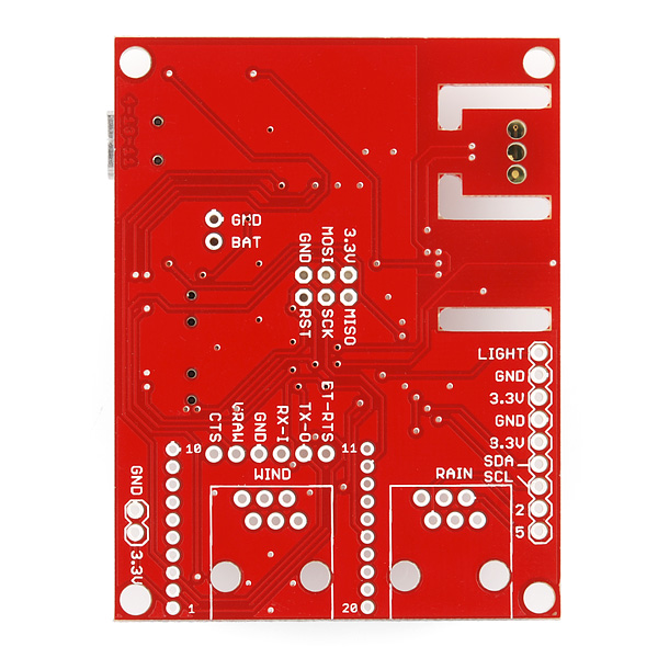
If you hold the board so the "Light" label is right side up, the solder jumper is the solder blob inside the white square immediately to the left of the light sensor. You don't need to cut anything, just heat and remove the solder blob so that the two halves are separated (solder wick is the easiest way to do this), and connect your external light sensor to the nearby header pins (labeled on the underside of the board). If anything is unclear, always feel free to ask.
Has anyone connected this using a WiFly RN-XV module SFN pn WRL-10822? If so does the firmware work with the WiFly module?
I, too, would like to interface a WiFly to this, but upon reviewing the schematic, it appears as though only 3 of the necessary 4 pins are broken out (D10(SS) is not, D11-D13 are). I'm not one to solder leads straight to SMDs so not sure if this is feasible.
Not to reply to my own reply, but now I see there is the WRL-10822 which looks to be hardware compatible with the XBee hardware but uses WiFi. Has anyone actually tested this with this weather board? There appears to be a picture of the setup on the WRL-10822 page.
I built up a clone of this board with all basic components, You can check out my work here. http://www.stoaks.net/index.php/2012/02/19/building-a-weather-station-clone/
Compiled perfectly. Thanks
New to both Weatherboard and Arduino so be gentle. I'm compiling the firmware V1.1 ( I will need to make some changes later) and coming up with some errors. The board is NOT connected yet.
3 have me scratching my head.
C:\Users\Bill\Desktop\arduino-1.0\libraries\SHT1x/SHT1x.h:18:22: error: WProgram.h: No such file or directory // the file is there. The version that came with the firmware so I'm not getting why this one.
Weather_Board_3.pde:-1: error: conflicting declaration 'const int SCK' C:\Users\Bill\Desktop\arduino-1.0\hardware\arduino\variants\standard/pins_arduino.h:43: error: 'SCK' has a previous declaration as 'const uint8_t SCK'
// these look related. But odd
Have I missed a basic setting in the environment somewhere ?
Oops! Good catch. Those errors are there because the firmware hasn't been updated for Arduino 1.0 (which has several features that are not backwards-compatible). You can try compiling it with an earlier version of Arduino, or wait a few days while we update the code. Watch this space for an announcement. Thanks for the bug report!
I am too much of a rookie to go back ! I have enough on my plate. Thanks for the lightening fast response.
We've updated the firmware for Arduino 1.0; it's available at the top of the product page. Please let us know if you find any problems, and have fun!
Do you SFE folks have a hex file image of the Version 3.1 firmware? It would be awfully nice to have a known good backup in case I manage to foul something up.
If you've used a hardware programmer to wipe the bootloader (encouraged!), you can restore it by first reinstalling the Arduino bootloader using the hardware programmer, then uploading the sketch over serial using the Arduino IDE.
Call me paranoid, but I still don't entirely trust the Arduino programming environment. "If it ain't in hex, it ain't real!" Certified dino-speak, eh? If I start saying, "Back in the old days...." shoot me! Please!
I'm going to feel rather stupid when someone answers this. But, at least I won't be (quite as) uninformed.
In the "Weather_Board_3.pde", there's an #include directive:
include <avr[backslash]eeprom.h>
Where do I find that header file?
Includes are often very hard to find, so don't feel stupid. On my system, avr/eeprom.h is in C:\Program Files\arduino-0022\hardware\tools\avr\avr\include\avr. Windows search is a good way to find deeply-buried files like this.
Thanks, Mike. I've got WINAVR, CodeVision, and AVR Studio on my system, and a Windows search just opened a floodgate. I've never used the Arduino IDE (I like CodeVision just fine!) but porting code just to make a few tweaks isn't worth the trouble.
So, can someone tell me exactly how they compile and upload code to this board? I've tried several versions, both firmware from here as well as alt firmware and none of the firmwares compile.
Can someone tell me how they've compiled the code, and how they were able to connect to the board to upload it? I've tried as a Uno, a ATMega with 328, etc. I pasted a copy of my error here: http://pastebin.com/vSNU8TK0
Actually I just looked on page 7, and saw instructions for how to connect. Will retry, thanks.
Yea, still get the same errors, I'll give it a rest for now, any help would be appreciated tho.
You should be able to use the standard Arduino IDE to compile and upload code to the board. The main gotchas I know are:
Make sure both switches are set to "USB" before uploading code.
Ensure you've set the Arduino IDE to the correct board type ("Arduino Pro or Pro Mini (3.3V, 8MHz) w/ ATmega328")
Also ensure you've selected the right COM port (you can check this in the Windows Device Manager)
If you're using a Mac, you may need to press the reset button on the board right when upload begins.
Do you own another Arduino product, and can you successfully program that one? If you're continuing to have problems, please contact tech support and we'll be happy to help you out.
So does this board support LiPo battery charging as well?
No, this board doesn't have an onboard charger, but you can use one of our separate LiPo charger boards to do so.
If you are interested, I have connected this weather board to embedded WiFi board called Carambola. See project details here: http://www.8devices.com/wiki_carambola/doku.php/carambola_pachube
Just curious if anyone has had success powering one of these from a solar panel with a lipo plugged in for overnight power? I'd like to mount this in the middle of a yard and use a solar panel to charge the battery during the day and still maintain sensor readings and transmission via an xbee.
sorry for being dump!! I am applying CTRL-Z combination but no change occur... no menu nothing.. I am using arduino serial monitor and also tried on hyper terminal.. but still no luck!! waiting for input.. kindly suggest what should i do now?
Got the answer!! my bad.. flow control should be none. .. with baud rate 4800.
I'm having the same issue, not getting any config menu when sending CTRL-Z, continues to to receive. Tried the above solution but unfortunately isn't working for me either.
i had this problem also, no matter what software i used. what i did was open up the code and change the:
if (Serial.read() == 0x1A) // CTRL-Z
to:
if (Serial.read() == 0x6A) // lowercase j
then all you do is press 'j' to access the menu.
Try a different terminal program (Tera-Term, Coolterm, Realterm, Hyperterm); the serial monitor built into Arduino isn't great at sending control codes.
Why is FAIL showing up on random lines of the boards output?
Using xBee, can communicate both directions (responds to +++ fine), can see the boards menu, getting data every 5 seconds.. But temperature, pressure, light and wind speed show FAIL at the end of their data lines...
Yesterday it was temperature and humidity.. What has Failed, why is FAIL(ed) being displayed?
Thanks
Every board we build is tested so that we know it was built correctly. To support this, the default ANSI mode in the supplied firmware will test each sensor output and display FAIL if it is out of range. The ranges were chosen to be reasonable for our factory floor where testing is done, For example, the temperature should be between 65F and 85F. If the reading is outside that range, there's either a problem with the board, or with our HVAC system. If you don't have the Weather Meters connected to the board, windspeed and rainfall readings of zero will show as FAIL since our test jig simulates input to those sensors. (Note that you can turn off data from the nonexistent Weather Meters via the menu).
If you're getting reasonable values for the actual sensor outputs for your location (which may have different conditions than our factory floor), than nothing has FAILed. If the actual sensor numbers do look very wrong (e.g. the temperature is 255F and you're still alive), then there's likely a problem with your board, and if you contact techsupport at sparkfun, we'll be happy to help you with it.
If you don't want the board to output these pass/fail values, you can switch to a different output mode, or easily alter the firmware to delete those statements. Hope this helps!
Very helpful. Thanks!
Was experiencing this with the BMP085 pressure reading. After re-visiting USB_Weather_Board_V3_datasheet_130705.pdf, realized I needed to adjust my station altitude since I was measuring relative pressure type (as opposed to absolute).
Prior to updating my station altitude I was getting a BMP085 pressure reading of "35.547 inHg FAIL". Further investigation showed that the lowest barometric pressure ever recorded is 25.69 inHg (Super Typhoon Tip) and the highest ever recorded being 32.03 inHg (Tonsontsengel, Mongolia). Once I corrected my station altitude (via CTRL-Z) my readings came in at an acceptable level of ~29.959 inHg, and the "FAIL" display went away.
I'm intending to add some extra I/O devices to this board, when it arrives. I was hopeful that the expansion connector would break out some of the unused microcontroller pins, but this doesn't appear to be the case.
However, looking through the code, it appears that RF-CTS, RF-RTS, MISO, MOSI, and SCK are connected but not used (Arduino pins D5, D6, D11, D12 and D13). Can anybody confirm this?
That's correct, those pins are available for your use. The expansion connector does breakout the I2C bus and power, making it easy to add additional I2C sensors.
Thanks Mike, I hadn't thought of using I2C. On reflection an Arduino Pro hooked up as an I2C slave is probably what I need.
Couple of questions.
1. How does this connect to the ARDUINO?
2. If I put a GPS on the ARDUINO, would it still talk to your PC via the Zigbee on the weatherboard?
New version of code for the USB Weather Board v3.0:
1.2 grualia release, 2011/08/18 http://www.grualia.com
Download in the link:
http://www.grualia.es/download/software/Weather/WeatherBoard3v12.rar
Functionalities:
- the sensor works as an altimeter
- with two sensors, we can run one as a BASE and another as MOBILE, where it can be more accurately adjust their altitude with corrections that will send the BASE
- fast menu
- the code does not fit in the memory of the micro, which are a compilation constants we can indicate what output format we want and if we want a description or a quick menu
We are very grateful that we use it and report any error. Thanks
In playing around with it, I can't set a working sample rate longer than 32 seconds. I'm guessing something is being stored or interpreted as an integer (32k value) and that's causing this funny business but I haven't found it in the code yet.
The problem is solved. You can put up to 1 send each 255 seconds.
Download in the link:
http://www.grualia.es/download/software/Weather/WeatherBoard3v11.rar
Ok, this tuesday we look the code for fix this problem. What sample rate do you guess? I think that maximum is a byte, 255 seconds, I dont't know why don't accept 32 seconds the code? We look it this the tuesday, ok?
Thanks for report problems.
We solve all the problems of the arduino code. In few days, we upload a version of code in our page. I hope that sparkfun's programmers haven't any problem.
1.0 initial release, 2011/06/27 http://www.sparkfun.com
1.1 grualia beta, 2011/08/12 http://www.grualia.com
1.2 grualia release, 2011/08/19 http://www.grualia.com
We are development project about (Research + Development + Innovation) (RDI).
We post here a link to download the new code.
I have bought the sensor USB Weather Board v3.0 .
A series of problems has happened to me on having been connecting / disconnecting to the sensor. When I have disconnected several times, and I return to connect, only it comes to me for the serial port the word "RESET" and already it does not come at all more...
I have been checking the code and have thought that it might be that exists any crash in the protocols I2C and have left a small delay after the line:
TWCR |= _BV(TWEN);
// Delay
delay(250);
// start BMP085 temperature reading
With this one line added, it seems that me the sensor goes better. But i'm not sure that with this it solves...
You has this happened to someone already?
I have connected weather board to weather meters. rainIRQ() interrupt routine is giving false counts. Any suggestions?
When the rain gauge switches, the switch contact mechanically bounces. A fast IRQ routine counts some of those bounces thereby giving a false reading. There are two solutions:
Hardware: check out the MC14490. It's a great chip for solving this type of problem.
Software: add a 100ms interlock to the IRQ routine. Get the current millisecond time and compare to last time IRQ was called. If less than 100ms, do nothing. If more than 100ms, update time of last IRQ and increment count.
Can you add an ethernet shield to this board? If so, could someone point me in the right direction on how to do so. Thanks!
The easiest way to accomplish this would likely be to send data from the Weather Board to an Arduino plus Ethernet Shield programmed to pass the serial text data to whatever Ethernet address/port you require.
Can I use lcd display with this board. is it possible?
Yup, it's all set to work directly with our serial enabled LCD displays.
Ok. I have sparkfun serial enabled LCD display. Can you tell me how can I connect LCD display to sparkfun weather board.
First, configure the Weather Board to output the LCD format using the menu, and save that configuration. Then connect the Weather Board's TX line to the LCD's RX line. The easiest place to do this is probably the XBee header JP6, which also includes VCC (3.3V) and GND to power the display (the bottom of the board has markings for pin numbering).
Metric isn't English?
Hopefully a future version can support data output compatible with Peet Bros. Ultimeter series. There's plenty of documentation for their formats.
It's confusing. Here in the US, "English" is a common term for non-SI units, though it's probably more accurate to say "imperial", or according to Wikipedia, "United States Customary Units" (bleh).
Great call on more data formats! The code is VERY easy to modify to output new formats, so don't be afraid of diving in if you need the board to do something special.
Also, can I change the temperature from F° to C°?
It's even easier than that - there's a menu option for English or metric. If you want Kelvins, you'll need to modify the code. ;)
You can use this formula to do so:
C = 5/9(F-32)
Check the firmware link above, you can change the code to output whatever you want.
Hi,
Can it be used with an Xbee different from the 1mW one? I need more distance.
Yes, it should work with every xbee module except for the XTend.
Since we're talking only relative measurements, why not use some Light Pipe - Clear Core 6 mm to bring "daylight" to the light sensor?
Great idea! The board has also been set up so it's straightforward to add an external light sensor.
Despite the "Got weather? This board can handle it." line, you probably should put this in a case before deploying:)
Or smother it in hot glue.