- Home
- Product Categories
- Sensors
- Triple Axis Magnetometer Breakout - MAG3110

Triple Axis Magnetometer Breakout - MAG3110
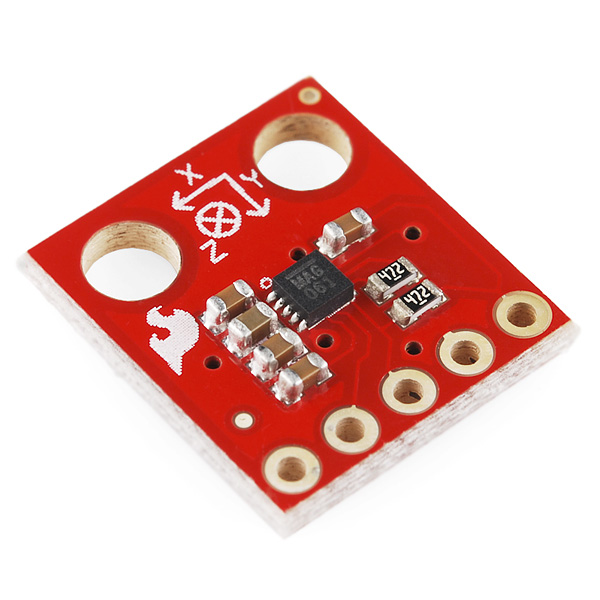
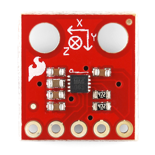
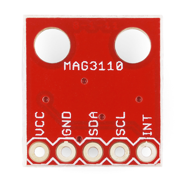
Freescale’s MAG3110 is a small, low-power, digital 3-axis magnetometer. The device can be used in conjunction with a 3-axis accelerometer to produce orientation independent accurate compass heading information. It features a standard I2C serial interface output and smart embedded functions. It's also a tiny QFN package which isn't very easy to play with so here is our easy to use breakout board. This board breaks out all of the pins for the MAG3110FCR1 to a standard 0.1" header and also supplies the necessary filtering capacitors so that you can easily use it in your next navigation project.
- 1.95V to 3.6V Supply Voltage
- 7-bit I2C address = 0x0E
- Full Scale Range ±1000 μT
- Sensitivity of 0.10 μT
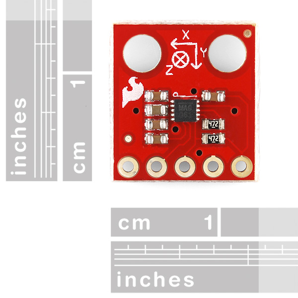
- 13.3 x 14.5 mm
- Schematic
- Eagle Files
- Datasheet (MAG3110FCR1)
- Example Code
Triple Axis Magnetometer Breakout - MAG3110 Product Help and Resources
MicroView Digital Compass
October 24, 2016
Build a portable digital compass using the SparkFun MicroView and the MAG3110 Magnetometer Breakout.
MAG3110 Magnetometer Hookup Guide
October 24, 2016
Get started with the MAG3110 3-Axis Magnetometer and learn how to make your own digital compass that senses the Earth's magnetic fields.
Core Skill: Soldering
This skill defines how difficult the soldering is on a particular product. It might be a couple simple solder joints, or require special reflow tools.
Skill Level: Noob - Some basic soldering is required, but it is limited to a just a few pins, basic through-hole soldering, and couple (if any) polarized components. A basic soldering iron is all you should need.
See all skill levels
Core Skill: Programming
If a board needs code or communicates somehow, you're going to need to know how to program or interface with it. The programming skill is all about communication and code.
Skill Level: Competent - The toolchain for programming is a bit more complex and will examples may not be explicitly provided for you. You will be required to have a fundamental knowledge of programming and be required to provide your own code. You may need to modify existing libraries or code to work with your specific hardware. Sensor and hardware interfaces will be SPI or I2C.
See all skill levels
Core Skill: Electrical Prototyping
If it requires power, you need to know how much, what all the pins do, and how to hook it up. You may need to reference datasheets, schematics, and know the ins and outs of electronics.
Skill Level: Noob - You don't need to reference a datasheet, but you will need to know basic power requirements.
See all skill levels
Comments
Looking for answers to technical questions?
We welcome your comments and suggestions below. However, if you are looking for solutions to technical questions please see our Technical Assistance page.
Customer Reviews
No reviews yet.
I need to know if I can use this sensor as a level! in my project I need to detect the orientation of my device and this device might be turned on in any orientation (therefore I do not have a reference orientation so I can use an accelerometer/gyro ) can I use this sensor, and if not, any suggestions ?
anybody?
Hi, I'm trying to do a burst read. I'm using the MAG3110 demo board above/w FreeScale's MC9S08 as the interface. I am doing the following: // X MSB IIC1C1 = IIC_Start; <---start signal IIC1D = IIC_Write; <--- 0x1C IIC1D = OUT_X_MSB; <--- x-axis MSB (0x01) IIC1C1 = IIC_Repeat; <---- repeat start IIC1D = IIC_Read; <---- 0x1D IIC1C1 = IIC_Stop; <---- stop signal
I keep getting 0xFF coming back to my data register, I can confirm this on the scope. It doesn't matter what I ask to read from the slave address the register always reports 0xFF? I thought I was suppose to get a burst of six bytes coming back, I only see one byte and its the same for everything??? Can someone help!
Hi, I'm trying to connect two Mag3110's to the same I2c Bus on an Arduino. Is there any way to change the slave address of 0x0E on one of the chips so that I can address both of them on the same bus? Thanks.
I am new to magnetic sensors, what is the difference between a magnetometer and a digital compass?
A digital magnetometer is the same thing as a digital compass.
Ok thanks, so what does the other 2 axis on a magnetometer provide you with? Angle in relationship to magnetic north?
Yup. That's why they are commonly used in orientation applications along with accelerometers. They just help increase accuracy of position calculations.
hello, two questions, you can connect 2 MAG3110 and view data simultaneously on a single arduino connect a single sensor .... no problem as calbro the sensor gives erratic values thanks
So I have found the mid point for my MAG3110 to be: x_offset = -114; y_offset = 113; z_offset = 122;
And my top reading after subtracting this about 32000... Not really 0.1 uT per tick here is it? :P Does anyone know how this is this scaled?
I can get readings that seems to be legit but it for sure doesn't spit out uT or even 0.1uT when just reading the data...
For example: (using FEZ Domino) x = (Int16)(receiveData[2] (backarrowbackarrow) 8 | receiveData[1]);
Will result in a value between -13553 to -7665... (when being stationary)
If we are not being magnetized as a species by 1355uT my scale or something is waaaaayyyy off! ;)
A little help please?
anybody can tell me what's the C compiler that are using in the example code. thanks.
It's code written for the Arduino IDE. You can download a version of it here.
Hello, I bought a MAG3110. And also I bought a USBI2C board to read the I2C. But the problem is that on MAG3110, there is the ''SDA'', ''SCL'' and also ''INT''. In the USBI2C board, there is no ''INT''. So how can I connect them? Thanks,
INT usually means an interrupt, in the case of a special feature on the chip. You can get the I2C to work without hooking up the INT pin.
Why is the reading from this magnetometer isn't the same as the WMM or IGRF models saying there is a large difference between them ???
The SDA and SCL inputs of the sensor's two wire interface specify a voltage limit of 3.6 volts (+/- a bit) and (if I'm correct) the outputs of the arduino duemilanove are at 5 volts; do people usually accomplish this voltage drop with a voltage divider or an op-amp, or is it even necessary?
I2C parts can only actively drive the SDA line to ground; for a logic-high signal, the line is left floating, and the pullup resistor determines the high voltage on the line.
If you are careful to power your 3.3V I2C part with 3.3V, and the pullup resistors are also connected to 3.3V, then you can safely connect a 3.3V I2C part to a 5V Arduino. (The Wire library will correctly not put a full 5V onto the I2C lines).
There is some controversy that the Wire library enables the internal weak pull-up resistors on the Arduino, which does put a weak 5V on the line. However, if you are also using external pullup resistors to 3.3V, the resulting voltage won't be greater than 3.6V, which is safe for the 3.3V parts.
tl;dr: in most cases this is safe to do. Hope this helps!
where can I get the Eagle library of the MAG3110 itself instead of the whole Eagle project? Im looking for the ".lbr" not the ".sch" or ".brd"
thanks
Hello,
I am running this chip on ARM SAM7 processor. But I am having problems with it. I also have other I2C sensors from sparkfun like BMA180, BMP085, TMP102 and they all run perfectly well, under my written software in I2C mode, except the MAG3110 which is driving me crazy...I checked all the addresses and everything in my software many times and everything is correct, but strange thing are happening. Once i write something to control registers 1 or 2 everytime I write something the chip factory ID changes. By default it is set to 0xC4, but depending on the values I write to control registers, like 0x01 to reg1 and 0x80 to reg to (like in datasheet example) I receive chip ID sometimes 0xFB, sometimes 0xEE, or 0xED...this is bullshit...I am not talking about mag values on XYZ axes which is total nonsense...Any Idea why this is happening to me? To be clear I connected only single chip to I2C, no other slaves. I have a hunch that the chip itself is faulty...if anyone have any other explanation please share your thoughts.
Best regards, Mantas
Is this a good compass or not? BecauseI am confused. if there is a better compass can you send me a direct link pls. this is urgent
Has anyone ever had luck programming these devices in LabVIEW in conjunction with a National Instruments USB-8451? Can you please post?
Hi,
I'm just got this device, and I'm trying to hook it up to a NI-8451 (http://sine.ni.com/nips/cds/view/p/lang/en/nid/202368) or a Diolan DLN series (http://www.diolan.com/comparison/dln.html) I2C to USB converter.
Some questions since I'm new to this.
1.) Which pins on this breakout board do I solder to? Obviously VCC and GND, but SDA is your signal, and SCL is your clock? Just double checking. Any special type of wire gauge?
2.) How about if we wanted to hook up more than one magnetometer to the I2C to USB converter? Anyone have any knowledge with bus expanders?
Thanks!
Yes SDA stands for serial DATA and SCL stands for serial CLOCK. You can hook up as many as you want considering that they have different addresses. Please read the datasheet before asking these questions. Everything is explained in detail there.
Best regards, Mantas
Actually if I understand this all correctly, the statement "you can hook as many up as you want considering that they have different addresses" is NOT correct... This device has a set 7-bit I2C address = 0x0E that cannot be modified. Therefore only one device can be on an I2C system and communicate properly...
SparkFun Team,
Why do you put the pull-up resistors for SDA/SCL lines on the breakout boards? It is rather easy to pull up these lines on the breadboard or in a custom board, but this practice makes it really difficult to attach several sensors to the same I2C bus.
I was trying for some time to make this breakout board and the one for MPU-6050 to work on the same bus and was getting strange errors until I noticed that each of the breakout board includes the pull-up resistors (4.7 KOhm for MAG-3110 and 2.5 KOhmn on MPU-6050), which put the bus out of specs.
Regards, --Alex
We go back and forth on this, and because people either need them or they don't, we get complaints either way. ;) We're leaning towards including them by default, for the following reasons:
One is that the simplest use case, connecting a single BOB to a microcontroller, should be as painless as possible. Not everyone has the extra resistors, or a convenient location in the circuit to put them in (for example, directly connecting a BOB to an Arduino). Another is that if you don't need them, you're getting into the intermediate and advanced skill levels. We figure that for such users, it's much easier to remove the pullup resistors from a board (you can easily knock them off with a soldering iron), than it is to find the correct size and footprint of SMD resistor, and solder them on, if you do need them (especially for a beginner).
For some upcoming boards, we're trying pullup resistors tied to NC solder jumpers, to make it easy to disable them if desired. We hope this is the best of both worlds.
Thanks for your feedback, and good luck on your project!
By "(you can easily knock them off with a soldering iron)," do you mean a conventional soldering iron or one intended for use with surface mounts? I'm only a little past beginner but know I need to remove them to work with another board. That said I really don't want to destroy another board.
One suggestion to Sparkfun is to make BOB with jumpers on headers, so the end user could decide whether he need a pull-up resistor or not for I2C bus, this way you will keep all customers happy!
Best regards, Mantas
Hi, I bought this sensor here in sparkfun and when run example code in Arduino 1 the result is: x=3320,y=-2750,z=-602 x=3323,y=-2755,z=-597 x=3323,y=-2752,z=-602 x=3317,y=-2751,z=-592
Any idea why the measurement are over 1000μT?. Supply voltage is correct=3.3V from arduino.
Thanks for any help.
First, the LSB is 0.1 uT, so to convert the result to micro-Tesla you need to multiply captured value by 0.1.
Second, as i noticed, this magnetometer has a huge offset (at least the one that I got) - for example, when I rotate the magnetometer the X value changes in the range of about 270 uT to 200 uT, while the proper range should be from about 35uT to -35uT. Looks like I need to load the x-offset register with something like -2350 (note: the user offset is applied to the raw measurement, which is calculated with LSB=0.1uT).
Hi,
does the magnetometer have a offset even after the factory calibration? With no other parts or disturbing objects around it.
Would be great to know Regards Jakob
Hello I've got the same problem even if I tried the offset method:
We are having issues reading back a useable temperature value. We read 252 from the DIE_TEMP register using an arduino, at room temperature. The X Y Z, WHO_AM_I and everything looks fine.
The register value increases as the temperature increases, until it overflows. Does anyone know the process that needs to be followed to get a useable temperature value? Conversion, offset ?
same problem here with arduino/temperature. Reading 253/254/255
I'm also having this problem, though I'm reading it out on a Raspberry Pi. I'm getting 0xFF (-1 C) most of the time, and occasionally 0x00 (0C), in ambient conditions around 25C. I never get any other values. Everything else works perfectly, except temp.
I've tried reading it both before and after the magnetic values (since the device seems to do some magic when you read the X MSB), and with and without delays in between them (just to see what's up). I've even tried reading all the registers at once, and I am getting correct values in every register, including those immediately before (Z user offset LSB) and immediately after (CTRL 1) the DIE_TEMP register. It's just DIE_TEMP that is haywire.
I know that -1C and 0C are both theoretically "valid" temperatures, but 0xFF and 0x00 sure look a lot like either hardware problems (letting SDA float high, or holding it low) or else programming problems (-1 and 0 are both often used as "error conditions").
Does anyone have one with a sane DIE_TEMP? Or do we just have faulty units?
EDIT: After doing some research, I found a newer datasheet ( http://cache.freescale.com/files/sensors/doc/data_sheet/MAG3110.pdf ) which indicates that the temperature offset is NOT set by the factory, the user has to determine the offset on their own (fun). After playing around with warming up the sensor, it appears that I was lucky/unlucky enough to get a sensor that just happened to have its 0 be at my current room temperature. I am now able to get temperature changes, so I am just going to assume that that is the problem for now unless I ever see it start drastically diverging from other temperature sensors I have.
SparkFun folks, can you update the link to the newest revision of the datasheet?
I'm not sure if this helps (after 11 months), but the DIE_TEMP register is in two's complement, meaning the value 252 would actually mean -4 °C. If you want to get dirty, you can call the MSb a sign bit and mask it with 0x3f.
A cleaner way to convert it would be through a union.
Why 3 dimensions? I understand x,y for N/S and E/W, but how would you use the z axis, especially if it’s not tilt compensated?
A magnetometer is not necessarily a compass. There are applications where it is useful to know the direction of a magnetic field.
Also, how sensitive are these? If I had it next to a hard drive would there be a significant distortion?
With either this or the HMC5883L there would be distortion is you put it near a magnet or a ferromagnetic material. That is why you need to calibrate the measurements you get from these. Freescale has provided an application note which explains how to correct this effects.
How does this magnetometer compare with http://www.sparkfun.com/products/10530 ? They are both the same price, both use I2C, so why sell both?
Any chance you will start selling this without the breakout board, just the IC?
No plans at the moment, but you can always get them (maybe even free samples) from Freescale
Hi, i bought this mag sensor as i want to use it as a compass, i loaded your code but when i rotate it (parallel to the ground) the values change very little, about 6 degrees.
I calculated the heading with:
float heading = atan2(readx(), ready());
float headingDegrees = heading * 180/PI;
and i get these values:
x=3398,y=-5064,z=-769
heading=146.10.
what do you think it could be the problem?
I tried to use this to calculate heading and i have for a full rotation 5 degrees of difference, between 55 and 60 degree:
int getHeading(float x, float y, float z){
float heading=0;
if ((x == 0)&&(y < 0))
heading= PI/2.0;
if ((x == 0)&&(y > 0))
heading=3.0PI/2.0;
if (x < 0)
heading = PI - atan(y/x);
if ((x > 0)&&(y < 0))
heading = -atan(y/x);
if ((x > 0)&&(y > 0))
heading = 2.0PI - atan(y/x);
return int(degrees(heading));
}
Hi,
Your problem is due to calibration. You need to correct the offset values, either by writing to the offset registers of the device (OFF_X_MSB ,etc) or by subtracting the offset from the measurements you get. This is caused by hard iron effects. Freescale has an application note (AN4246, i think) which explains this effect and how to correct it.
You can correct the measurements by subtracting an offset from the measurements ( the offset for each axis is (max_measurement + min_measurement)/2 ). This should give you good enough readings. But if you want to be more accurate then you can collect readings while rotating the magnetometer in every direction and fit the measurements to a ellipse. An ellipse is described by the equation x'Ax = 1, where x are your measurements. You need to find, using least squares, the values for the matrix A. After that, you can find the transformation that rotates and scales the ellipse into a circle by taking the Cholesky decomposition of A = L'L. With that, for every measurement x you get, you can get x_corrected = L*(x-offset_vector), and your measurements of the heading will be much more accurate. The only thing that is missing is to add an accelerometer to compensate for tilt
So.. can this be used like a compass? ie a xy plane point of reference for orientation.
Yes, it's used exactly like a compass.
Be warned though, these are sensitive to radio transmissions from stuff like the Xbee, WiFi, and your cellphone.
Does anyone have any experience to compare this with the Honeywell mags?
I don't have any experience, but: 1.This one can go to a lower voltage: 1.95V versus 2.16V. If you are doing any battery powered application, you can save some power by running this as low as possible.
This one is more sensitive. 0.1µT = 1mG; the other one is 5mG.
There are a lot more in the datasheets, varying from maximum magnetic field to idle current... take a look.