- Home
- Product Categories
- Sensors
- Tilt-a-Whirl Breakout - RPI-1031

Tilt-a-Whirl Breakout - RPI-1031
Replacement:SEN-12011. We have a new rev of this breakout which fixes a few silkscreen issues, go check it out! This page is for reference only.
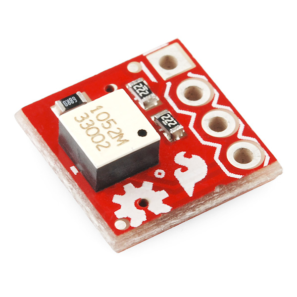
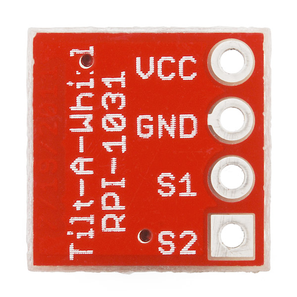
The RPI-1031 tilt sensor is capable of sensing a change in orientation in four different directions: forward, back, left or right. This breakout board makes it easier to incorporate the RPI-1031 in your next project by breaking the necessary pins out to standard 0.1" spaced headers. This board will work at either 3.3 or 5V.
- Schematic
- Eagle Files
- Datasheet (RPI-1031)
- Product Page (RPI-1031)
- bildr Tutorial
Tilt-a-Whirl Breakout - RPI-1031 Product Help and Resources
Core Skill: Soldering
This skill defines how difficult the soldering is on a particular product. It might be a couple simple solder joints, or require special reflow tools.
Skill Level: Noob - Some basic soldering is required, but it is limited to a just a few pins, basic through-hole soldering, and couple (if any) polarized components. A basic soldering iron is all you should need.
See all skill levels
Core Skill: Programming
If a board needs code or communicates somehow, you're going to need to know how to program or interface with it. The programming skill is all about communication and code.
Skill Level: Competent - The toolchain for programming is a bit more complex and will examples may not be explicitly provided for you. You will be required to have a fundamental knowledge of programming and be required to provide your own code. You may need to modify existing libraries or code to work with your specific hardware. Sensor and hardware interfaces will be SPI or I2C.
See all skill levels
Core Skill: Electrical Prototyping
If it requires power, you need to know how much, what all the pins do, and how to hook it up. You may need to reference datasheets, schematics, and know the ins and outs of electronics.
Skill Level: Noob - You don't need to reference a datasheet, but you will need to know basic power requirements.
See all skill levels
Comments
Looking for answers to technical questions?
We welcome your comments and suggestions below. However, if you are looking for solutions to technical questions please see our Technical Assistance page.
Customer Reviews
No reviews yet.
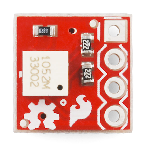
This board uses a LED input resistor value of 68 ohms; as a result the absolute maximum rating of the LED in the sensor will typically be exceeded when powering this board with 5V. A better value would be something like 390 Ohms (or 220 Ohms for 3.3V operation). At reduced LED current the load resistors (the 2.2K resistors) might need to be increased too (like maybe to 20K or so). This board should be able to work at any operating voltage from 3V to 5V and consume 10 mA or less with appropriate resistor values in place.
68R is definitely to little. BOB gets hot after 2 minutes of use! SparkFun, can you verify that 68R will not burn out/damage the LED?
trying to get this chip to work using SWORDFISH but I keep having to reset the pic to check tilt. Device = 18f2420 Clock = 8 //Config OSC=HS Include "InternalOscillator.bas" Include "utils.bas" //Include "convert.bas" Dim s1 As PORTC.4 Dim s2 As PORTC.5 Dim led2 As PORTB.3 Dim led1 As PORTA.3 Dim x As Byte Dim tilt As word
Dim position As Word dim tilt_pos as integer dim index as integer Input (s1) Input (s2)
led1=1 led2=1 //tilt_s1 = 2 //tilt_s2 = 3
Output (led1) Output (led2) SetAllDigital
While true
EndIf if tilt = 1 then led1 = 1 led2 = 0 delayms (1000) led2 = 1 // leds off led1 = 1 endif tilt = 0
any suggestions
code does not work here or on the bildr website returns error sketch_jun03a.cpp: In function 'void loop()': sketch_jun03a:12: error: 'getTiltPos' was not declared in this scope
fix the code! It's so simple. Your error says "‘getTiltPos’ was not declared in this scope" this mean it does not exist, was not declared! Read the code and look, you ask for int position = getTiltPos(); This mean that there is a function call getTiltPos(); check your 17 lines of code and see if you can find getTiltPos()... no it's not there. That is why you get that error. Instead what you will you find is getTiltPosition()! This mean that you need to call that function instead. Your code will now be int position = getTiltPosition(); Now you will be able to get the Pirection of your Digital Steal Camera!
these are some great tilt sensors!
I had a couple of these to put on my own boards. A little too much time under the heat gun makes the top cover come off. The 'ball' is actually a small cylinder that can completely cover one of two detectors or the lone emitter. It cannot rotate along the perpendicular axis, as it is just as wide as the chamber it moves within.
Anyone have some arduino code for this device they'd be willing to share?
I'm an idiot. But just in case there are others out there... the below code works fine. Apologies for the funky formatting...
const int s1_pin = 13; const int s2_pin = 12;
void setup() {
Serial.begin(9600);
}
void loop() { int s1 = digitalRead(s1_pin); int s2 = digitalRead(s2_pin);
Serial.print( "S1 = "); Serial.print( s1 ); Serial.print( "; S2 = "); Serial.println( s2 ); delay(250); }
Tried the example code but always returned s1=0; switched s1 to pin 11 and problem solved (someone smarter than me can explain why).
Mounted horizontally the sensor needs to tilt about 25 degrees before change of state.
That silk is extremely offset.
Resistor soldering looks a bit dodgy...
It shouldn't affect the durability or usability of the board much.
For a sensor that detects tilt, one would expect some specification in the datasheet that indicates the amount of rotation before the output changes state.
Unless I missed it, this important info was omitted.
However, as Chris stated, we can be assured that the sensor can detect the Pirection of your Digital Steal Camera.
It would seem that the suggested use is to mount the device perpendicular to your plane of interest, in this way it can tell which of its four sides are facing the ground... meaning that the state will change every 90 degrees about halfway between each side. because it's based on a photo-interrupter, you may find that the effective angle will depend on whether the sensor is stationary, after all it's essentially a ball rolling inside a square channel.
I suspect that mounting it on the horizontal plane will result in a useless reading (ball just free-rolling) until you tilt it in one direction or another in which case you'll probably only need to deflect it by a few degrees.