- Home
- Product Categories
- Kits
- Max Power IR LED Kit - Old Version

Max Power IR LED Kit - Old Version
Replacement: KIT-10732. The new board corrects the mis-wired transistor problem and allows the board to drive the 50mA for which the LED is rated. This page is for reference only.
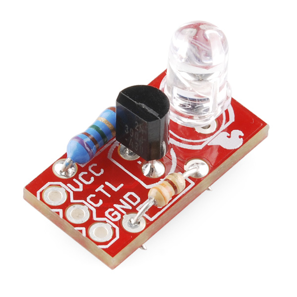
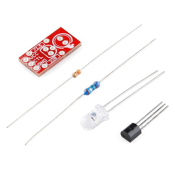
Infrared LEDs are awesome. Along with an IR receiver they can be used for remote control and even basic remote data communication. The only problem is that your Arduino won't drive them to their full potential. The Max Power IR LED kit solves this problem by providing you with everything you need to drive a 950nm IR LED properly. Simply solder together this easy through-hole kit and you can switch the LED using a transistor.
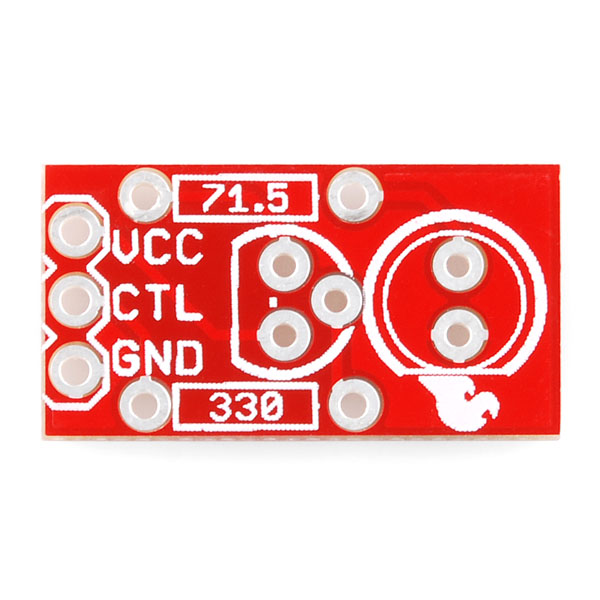
Once the kit is assembled, simply provide it with voltage (5V), ground, and connect the CTL pin to a digital pin on your Arduino, and you can drive this kit just like a normal LED. Although the LED won't be visible to your naked eye, you can use a video camera, cell phone camera, or digital camera to see if the LED is working properly.
Note: We made a design mistake with this board and so it doesn't quite reach the 50mA maximum current that the LED is rated for. However, we are still measuring about 48mA through the LED which seems to work quite well.
- Schematic
- Eagle Files
- Datasheet (IR LED)
Comments
Looking for answers to technical questions?
We welcome your comments and suggestions below. However, if you are looking for solutions to technical questions please see our Technical Assistance page.
Customer Reviews
No reviews yet.
Design mistakes, silk screen mistakes... I know you guys eventually get it right but maybe you should assemble a couple of 'beta' boards to check out before committing to a production run. Some of us might be willing to beta test a new design for you if we get, say, 10 bucks credit for every mistake or viable suggestion we come up with.
Money? If I keep the boards I will do it for free! Although I know someone will end up enrolling in the program just for selling the boards on eBay. Maybe a buck per mistake / useful suggestion. At the end of the month they do a deposit on your Paypal account.
They make a lot of boards, which translates to a lot of mistakes.
That would be awesome :D maybe not $10 per mistake, i mean here that's three free kits, but $0.50 or $1.00 would be sweet.
I love this idea!
This is a brain damaged design, which is why it's hard to get it to work right. Normally the LED & resistor would be on the collector side of a NPN transistor, not the emitter side as in this circuit. The design should target about 5 mA of base current to ensure that you'll get 50 mA of collector current from a 2N3904. The Vf of the IR LED will be lower than the datasheet value of 1.4V (typically 1.2V to 1.3V, because the 1.4Vf value is at only 20 mA). And don't forget about the collector-emitter saturation voltage when calculating the LED current limiting resistor value; it's not large, but it's not zero either.
So, putting the LED and LED resistor on the collector side and assuming the LED Vf at 50 mA is 1.25V and the transistor saturation C-E voltage is 0.2V, we have (5V - (1.25V + 0.2V)) / 0.05A = 71 Ohms for the LED resistor. And the base current limit resistor for 5 mA base current is 5V / .005A = 1000 Ohms. Try it; you get exactly 50 mA through the LED and it's a no-voodoo design. You can also use the circuit at 3.3V with a LED resistor value of 37 Ohms and a base resistor value of 660 Ohms.
You can implement the corrected circuit on the existing PCB by flipping both the transistor and LED around and reversing the power supply polarity.
Oh come ON, this design is not complex, or original, or strange; it's actually straightforward and simple, and, you're not the first one to make this - at all. SF is a big company, don't go hard on things like this.
I agree. An LED is a Light Emitting Diode, so naturally it goes on the emitter. ;D
Actually, with most LEDs as the current increases the Vf also increases.
I agree. Seems like the logical way to do it.
Its a minor thing...but 48mA across the LED?
Apparently, they are using a special type of transistor that uses the voltage through the resistor to flip on and off. XD
[comment removed by author]
The joke is that voltage is measured across, and current is measured through.
Sparkfun is by far my favorite electronics website, I literally browse components for hours going through examples/eagle file's/comments ... learning, how many other company's compare? Dont freak out!
hello im new to electronics, i am just wondering what is an Arduino, and what would it be used for in this case, or any other case.
Check out our tutorials section. There is a lot of information there. You can also check out the homepage for Arduino at www.arduino.cc
I wasn't the only one who thought this.
You know who you are.
I've never seen an NPN tied to the positive side of the supply. Was this meant for a PNP perhaps? seems like an odd design choice.
I do it all the time. The collector collects power, which of course comes from the positive side, because ground is 0V, and + is... more than 0V.
WOW you guys suck! i sent you this idea and everything. I even made mines way before you did.
http://atomsofttech.com/store/index.php?_a=viewProd&productId=3
Mines is cheaper also!
I dont mind that you sell a similar product but how come you couldnt email me back that you where going to steal the idea?
May 9 2011 email: (Got No response)
Hi Jason,
Thanks for getting us this information! I will pass it along to our research department, who will be in touch with you if they are interested in your product. They do get a lot of requests, so there is no guarantee that you will hear a response from them, so please keep this in mind. As we are also in a different department, Tech Support cannot provide status updates for widget submissions.
If you have any other questions or comments, please let us know.
Have a great day!
Toni
Spark Fun Electronics Tech Support
6175 Longbow Drive Suite 200
Boulder, CO 80301
techsupport@sparkfun.com
1-303-284-0979
But is yours Sparkfun red?
I can get it red, blue, green, white, black depends .. Heh red is more of a sparfun thing so i tend to stay away from it :)
Black? Would that be a dark emitting diode (DED)?
I need one of those now.
Talking about the PCB heh
Sorry you feel this way. For what it's worth, this SKU was generated April 19th of this year. The idea and prototype were made well before that. The PCB's were ordered that same day as well.
We hope you don't feel like we profit from stealing other people's designs. It is a simple design so many people have probably come up with something similar.
I know this company is good just hate to see something so similar at about the same time mine was released.
If you made this so long ago why did you have a silk screen issue? Just wondering. I wont stay mad for long heh sparkfun is too cool.. Just had to let off steam
Sourcing 10 of something can be quick, but sourcing several hundred takes longer. Plus, we have a lot of other factors (engineer's time, setting up the builds with production, etc).
The boards were already on order before the issue was realized. We don't like wasting products. We found it to be perfectly usable, contrary to what other people are saying. I've tested it, and it works fine, it's just not ideal.
Ah i see, being a larger company does have some draw backs...
Of course :-) It has benefits as well as detriments.
What is the design mistake and could it easily be fixed at home?
You can get the 390 ohm resistor here and the 68 ohm resistor here.
change R1 to 390 ohms and change R2 to 68 ohms
This gives 50.03 mA through the LED
Its a tiny bit high but you should be fine. Increasing R1 more will lower the current (at 400 ohms its 49.97 mA but you might be pushed to find a 400 ohm resistor.)