- Home
- Product Categories
- Arduino Shields
- SparkFun LiPower Shield

SparkFun LiPower Shield
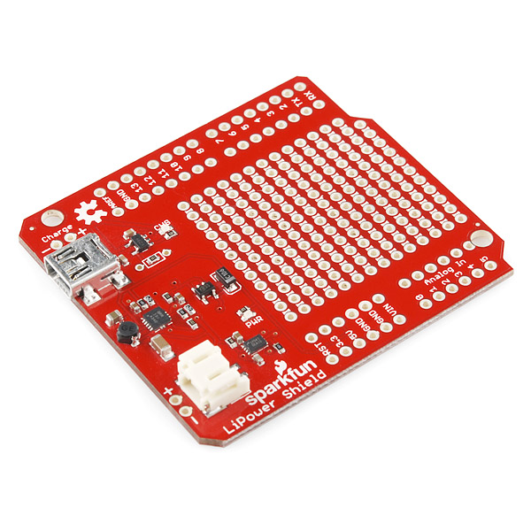
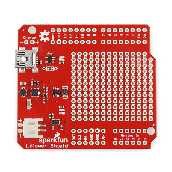
Is there anything an Arduino can't do? Well, for one, most of them can't be powered directly from a 3.7V LiPo battery; much less charge and monitor that battery. The SparkFun LiPower Shield takes care of this by combining the functionality of two of our favorite battery power boards: the Power Cell and the Fuel Gauge.
The LiPower Shield allows you to connect a 3.7V single cell Lithium polymer battery which it will boost up to 5V and connect to the Arduino board's 5V pin. The on-board MAX17043G+U IC is connected to the I2C lines (A4 and A5) so that your project can monitor it's own power supply. The configurable alert interrupt pin on the MAX17043G+U IC is broken out to D3 which will activate when the LiPo gets to 32% or lower.
The charging circuit is configured to charge the LiPo at 100mA but by adding a resistor to the supplied through-holes you can boost this to 500mA. There is a mini-USB port on the shield which allows you to charge the battery from a USB power source or you can supply a separate regulated 5V source on the "charge" header.
Note: We've decided to leave the power indicator LED (LED1) and its current limiting resistor (R3) off this board, as they were producing a significant drain on the battery. Please be aware that your board will have a few, shiny, unpopulated pads.
Note: There is a known hardware bug that will allow the LiPo to discharge below the point where the charging circuit will revive it. Thanks to the on-board fuel gauge, however, some clever programming could keep your project from draining the battery as it gets too low.
- Schematic
- Eagle Files
- Datasheet (MAX17043G+U)
- Datasheet (MCP73831T)
- Datasheet (TPS61200)
- Example Code
- GitHub
SparkFun LiPower Shield Product Help and Resources
Core Skill: Soldering
This skill defines how difficult the soldering is on a particular product. It might be a couple simple solder joints, or require special reflow tools.
Skill Level: Rookie - The number of pins increases, and you will have to determine polarity of components and some of the components might be a bit trickier or close together. You might need solder wick or flux.
See all skill levels
Core Skill: Electrical Prototyping
If it requires power, you need to know how much, what all the pins do, and how to hook it up. You may need to reference datasheets, schematics, and know the ins and outs of electronics.
Skill Level: Rookie - You may be required to know a bit more about the component, such as orientation, or how to hook it up, in addition to power requirements. You will need to understand polarized components.
See all skill levels
Comments
Looking for answers to technical questions?
We welcome your comments and suggestions below. However, if you are looking for solutions to technical questions please see our Technical Assistance page.
Customer Reviews
No reviews yet.
Please a header pins with jumpers between the battery connector and the sheild circuit? I would buy more if you add this. I would like the ability to turn off power from the battery using a non physical contact reed switch circuit. This would allow one to turn on power or kill power to the Arduino project and prevent the battery from draining to low. See the following link for an example I have running. I have another version that uses 2 reed switches. The second one allows you to tell Arduino to kill the power from the battery. http://forum.sparkfun.com/viewtopic.php?f=14&t=25041&p=114873#p114873
I second this (or something like it). I'd like to use something like the Pushbutton Power Switch together with this shield to turn off my project's power usage.... https://www.sparkfun.com/products/8904
I think its time to update this product :)
Has anyone used this with the 2.5k resistor installed to get 500mA out of it? The MCP73831 gets REALLY hot, really fast. In reading the datasheet, it says it has thermal protection, and will throttle the charge current based on temperature of the chip so I'm not so concerned about it breaking, but does anyone know if it will maintain a 500mA charge rate, or if it falls behind once the chip gets super hot. Should there be a small heatsink on that chip for 500mA charging?
Something I noticed, once it gets really hot, it cools back down and runs at a cooler temperature (Even on a
Is there any connection on this board to detect that the circuit is charging? On my LCD I am displaying a battery gauge but would like to replace it with a different symbol when the circuit is charging.
What may happen if I plug the Arduino to USB to upload some sketch with connected LiPower Shield with battery attached?
That would not be a healthy thing to do. The Uno's power circuitry connects the 5V pin to USB power whenever Vin is less than 6.6V. The LiPower shield doesn't supply Vin, so you'd end up with the output of the 5V step-up regulator on the shield shorted to the USB power on the Uno.
Doesn't that mean the example code is inherently dangerous? (Sorry to zombie your reply.)
If you disconnect the charging cable, will the arduino continue running off of the battery without being reset?
Help will be much appreciated:
1.) Where must the resistor be connected in order to boost mA to 500. The datasheet mentions pins 2 and 5 on the PROG and VSS. And the product description mentions "supplied through holes". Can someone please give a more specific location of where and how to connect the resistor.
2.) Is there any wiring necessary to have the lipo battery power the arduino? I soldered pins so that the shield can be placed directly on the arduino. However, when I connect the battery to the lipower shield, the arduino does not power. Am I missing something?
-------------------- Tech Support Tips/Troubleshooting/Common Issues --------------------
1.) Charging Circuit
Are you talking about the charging circuit's current rate? The best is to look at the LiPower Shield's eagle files in the document's sections to highlight where the programming resistor is using the eyeball tool. The charging circuit's programming resistor should be right next to the mini-B connector on the shield. Currently, the default is 100mA since there is a 10kOhm surface mount resistor populated on the board. You can add a through hole resistor where R10 is located (2.5KOhms for maximum current charge as noted in the schematic) to change the default charge rate.
2.) Booster Circuit
The development/breakout boards that are produced by SparkFun are usually tested on a pogobed and inspected by a technician for quality control before they are packaged and sent out.
The booster circuit might have been damaged if the Arduino is not receiving any power. Using a multimeter with its continuity setting, try checking the battery output pins. If there is a short, the IC might have been damaged due to a conflict with the power source if you had the Arduino plugged into the computer while also charging the LiPo battery through the mini-B connector.
How to use 4.1 volt instead of 4.2 ??
PLEASE HELP ME !
How can I change the charging voltage to 4.1 volts ? I read the datasheet and loking on the net ... I found nothing about it ! If there is no way can I just add a diod before the battery, and the internat voltage drop of the diod will do the job ?
Could this be combined with the "Wake on Shake" (SEN-11447)? How would you wire the battery so that the battery could charge, without having to wake the circuit? Parallel?
Also, I saw in a comment here that you can't have a battery connected while using the USB on the Arduino UNO, so that means you would have to do all the debugging and coding before the battery is connected, and then hope it all works? Unless you connect the Rx and Tx connections only to a PC to get the values...
Don't understand why this board cost $30. It should cost half as much or less.
I'm working with 2-Cell LiPo batteries of 7.4V, 2200 mAh. Anyone here knows an integrated circuit like MAX17043G+U that monitors my batteries?
Anyone have a good source for a 2.5k resistor? Every place I look has 2.2k or 2.7k, but no 2.5k.
This board is not reliable at all. I have had 4 of them fail on me over the course of 6 months. Tech support replaced 2 for me (one of which was DOA when I received it - and would not do so until I sent the boards back to Sparkfun for their testing, and then tried to say it was all my fault, DOA on arrival, no voltage from board - I don't think so). The others seem to fail after being in use from 2 weeks to 3 months. Only powering an Arduino PRO and an XBee so not anywhere near the current limit. Also made sure to watch the dual power input (batt and Arduino at same time - bad design that 2 diodes probably could solve). If you want stable power backup and control this board IS NOT the way to go. Just today lost another in a remote location so back to the drawing board to find something (anything) that is more bulletproof. DO NOT RECOMMEND if you want reliability. I still have 2 left but that is because they are still on the shelf.
I am using this in conjunction with the USB Host Shield. The Host Shield gets its power from the VIN pin, and it's less than 5v when using the LiPo SHield, causing my devices to not stay powered on. Is there a way to provide a full 5v to the USB Host Shield using the LiPo Shield??
I wrote up some details on the hardware bug in this shield on my blog.
http://vvishnyakov.blogspot.co.uk/2013/02/documenting-hardware-bug-in-sparkfun.html
As well as some details on using the example code and further notes.
This is phenomenally helpful. Thank you!
Not happy, One board arrived totally dead and the other one only worked for a few hours with a small picaxe before going to, it seems the Boost converter has died internally and shorted, one got very hot as it died, load is under 10ma... except for a split second on powerup where a small cap on the power rail is charged for the purpose of power smoothing: 470uf. Power is controlled with one of the Polu Pushbutton electronic power switches which is fine....
Picaxe by itself uses 5ma and the LED uses 4ma.
im sure the IC has internally gone on the one that did work, when i plug a battery in i might get a quick blip of voltage if im lucky then the battery protection circuit on the cell itself trips basically right away, and on USB which measured at 5.03V the IC gets very toasty, as in instant burn to finger. had a look at the traces and components with a USB microscope and found absolutly nothing. Eitherway thats $60 down the drain and im Pi$$ed!
Mine is also dead, I'm waiting for a reply from tech support.
Hey there! I'm with the Customer Service team here at SparkFun. Have you contacted our Tech Support group about this? We'd love to help you out - if you'd like to contact them (techsupport at sparkfun dotcom) they can troubleshoot the board and figure out what needs to be done (repair, replacement, refund - depending on the issue). :)
-Casey
Taylor Iversen has forwarded my email to Techsupport for me already, but refund might be the way to go for now seeing as shipping costs to get the two boards replaced + the effort and time involved in waiting wont be worth it for a while......
It would be good to have two selectable versions of the current devider in the feedback-loop of the TPS61200. One for 5V and one for 3.3V. I have to change the resistors to use the shield with the arduino mega2560 3.3V :-(
Does the alert pin (D3) need to be supplied with Vdd (+) and used with a resistor? I see it is labeled an input in the example code.
I believe I need to add I2C pull-up resistors on the SDA (A4) and SCL (A5) lines. What size resistors should I tie between each line and Vdd (+)? I'm assuming 4.7K ohms for the MAX17043G+U IC. Is that correct?
Please see my post in the Arduino forum that directly relates to this shield and problems I'm having. Any help is appreciated. Thank you.
http://arduino.cc/forum/index.php/topic,140371.0.html
I'm trying to power an Arduino (Duemilanove) plus three servos from a battery. Using the LiPower Shield with a LiPo 1000mAh battery causes the Arduino to reset itself whenever I try to manipulate the servos.
I've seen people recommending using two separate batteries, but then I'd need to be able to charge both of them and ideally monitor the levels of both of them and so on, which seems like a lot of extra complication.
Is it possible/likely that a single 2000mAh or 6Ah LiPo would work? They're also described as 2C, but given the higher capacity, I assume that the the same "C" value means more actual current can be drawn (and I further assume that the reset problem I'm seeing comes from the battery not being able to provide sufficient current).
I expect I could instead go with a 7.4V 25C two-cell LiPo battery pack, connected directly to the Arduino VIN instead of using the LiPower shield – that should work right? The downside is I can't monitor the battery level in software since there doesn't seem to be a fuel gauge that works with those.
Thanks for any tips.
I think I'm going to try a 7.4V 25C two-cell LiPo battery pack, plus the "AttoPilot Voltage and Current Sense" as a surrogate fuel gauge.
is this supposed to short your arduino? it does that to mine and gives the board no power whatsoever
What does this statement mean in the example code? How do I know what to set it at? It is probably the cause of my problem.
define MAX17043_ADDRESS 0x36 // R/W =~ 0x6D/0x6C
Why is no one from SparkFun tech support posting what the known hardware bug is in this design? If the problem is the UVLO setting a simple change of R9 from 220K to 200K will set the UVLO point to 2.75V (or change R7 from 2M to 2.2M)
What size resistor to charge at 500mA? What are the cons for doing this?
"The charging circuit is configured to charge the LiPo at 100mA but by adding a resistor to the supplied through-holes you can boost this to 500mA."
According to the schematic, a 2.5K resistor should be placed on R10 for maximum charge current(500mA).
I purchased three of the Power Cell, which share this schematic, for use with XBees, and moved the solder jumper to 3.3v. Of the three, one entirely failed to work, and another output 4V, destroying an XBee. Since the shield's power bypasses the Arduino's regulator, this same problem will destroy the Arduino this is attached to.
In addition, the EN pin of the TPS61200 is grounded and not accessible. This makes it impossible to switch the Arduino off without removing the shield altogether, and the shield drains at least 10mA per hour when not even connected to an Arduino.
Purchase this product at your own risk.
In re. to the PowerCell: Please contact techsupport at sparkfun dot com. You either have defective boards or you are using the boards incorrectly. Tutorial on how to use the PowerCell can be found here.
I don't think this shield is capable of fixing the problem even with "clever programming". The best you can do is put the MAX17043 into sleep mode, which will save power....but won't remove the load of the Arduino. You can also put the Arduino into sleep mode, and that will extend the life even further, but still won't remove the load enough to give weeks or months of extended battery life. A typical full-size Arduino will still draw 5-10mA even when in sleep mode due to the voltage regulator and other bits.
We really need this as a standalone board. not a shield. Just have the fuel gauge, boaster and charger all in one. then just have a set of break out pics, 3.3v, 5v, GND, SDA, SCI, ALT, then also maybe 2 jst, battery in, battery out. and I think a barrel jack would be better.
Anyone else run a lipo down until the undervolt protection kicks in and have the boost converter die? I'm trying to determine what caused mine to. My original theory was the low input voltage was causing excessive current in the converter, but now that I think of it, it shouldn't have been to excessive. The only load was an arduino running blink.
I've just received the shield and the charging LED goes on as soon as I plug the charger, even if there is no battery connected. Is this supposed to be so?
The schematic shows that the red charging LED is connected directly to vSource, so it will come on as soon as you apply power.
I bought one of these, hooked up a PRT-00341 (850mA lipo), charged it up with the USB. It worked. Because I wasn't ready to use it with my project, I threw it in a drawer with the battery connected where it sat for a couple of weeks. (It wasn't connected to an Arduino during this time.) Ready to use it, I pull it out and the battery is dead and won't take a charge. I've tried other power supplies to revive the battery but it seems dead.
Admittedly, I'm not an engineer, just a tinkerer, but it doesn't seem right that a) the lipo shield would discharge the battery and b) the battery would go below the minimum voltage protection. Am I wrong on either account?
Ah, I just found the second note in the product description. "There is a known hardware bug that will allow the LiPo to discharge below the point where the charging circuit will revive it."
Well, that kind of sucks. I didn't have my drawer cleverly programmed. Still, the battery itself should have prevented it from happening.
Wait a minute... I challenge the assumption that programming could fix the problem. Even knowing that the battery is running low, software can't prevent the board from discharging the battery.
According to tps61200 datasheet, the max current we can source from it is "600 mA Output Current at 5 V (VIN ≥ 3 V)". Is it possible to improve this max current? Thanks.
Possible bug? I couldn't see any I2C pull-up resistors on the MAX17043 (schematic dated 3/5/12). I couldn't see any on the official Uno board schematic either. Am I missing something? By comparison, the LiPo Fuel Gauge TOL-10617 has 4K7 pull-ups on SDA and SCL.
The Arduino Wire Library enables the internal pull-ups on these lines, but if you are using it with something else you might want to add them.
How much power can be pulled from a LiPo Battery to an isolated bus (to run a bank of servos for example) from the shield? If I can tap into the 5V supply without drawing through the Arduino, where should I draw the high current?
guys, I've connected the lipower shield to a mega 2560 rev 3 and uploaded the code from example code, but in console I only get "Hello World", am I missing something ?
You might want to take a closer look at your board. I had the same issue and also was "not" getting any power to and from the battery. I looked through the schematic and product pictures and noticed that my board is missing some components but have pads where they are supposed to go.
Hi,
Could you elaborate a bit more about the known hardware bug and how to fix it?
Thanks.
well i kinda made this myself awile ago. i had a lipo battery and the powercell charger
so i made 2 switches, one is just a battery disconnect (because just having the battery connected to the powercell it drained the battery) and the other switched between running off the battery and charging the battery. the switches work properly (aslong as you remember witch one is witch.)
for the fuel gauge (doesnt work properly) i tried just taking the 3.7v positive line from the battery and hooking it to an anolog input.
What is the bug referred to in the note? Is it lack of under-voltage lock-out on the 3.3V regulator?
Selfishly, I'm hoping it is something to do with the regulator because I've just designed a board with a MCP73831T and MCP1640 on it and don't want the battery over-discharging :(
Hopefully someone from Sparkfun will elaborate...
The schematic shows UVLO set at 2.52vdc. The LiPo batteries I use want their UVLO set to 2.75dc, so I'm wondering if this is the "hardware bug"?
Should I use this shield as Uninterrupted Power Supply (UPS) likes in PC area. Does it supply the battery power at once the USB power is off, and resume to normal once the USB power is back?
What is the purpose of the double rows of header holes? Just curious!
Every shield with a prototype area should have these double rows - it allows you to actually connect to the Arduino pins, even if a stacking header is used.
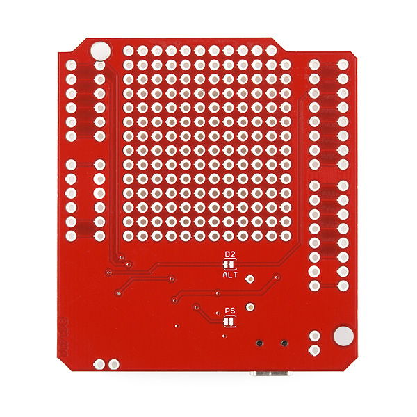
Yep - If you look at the bottom of the board closely, you can see all the Arduino pins are ganged to the 2nd row of pads. This allows easy access to all the Arduino signals for prototyping, but you can also cut the short trace and easily reassign the signals on this shield to other Arduino pins.
Also, it is worth pointing out that the prototyping area isn't just a grid of pads - they are bussed. So, unless you limit yourself to SIPs, you will probably need to cut bus traces to use the prototyping area.
I would have liked it if a mechanical power switch were included. Something that disconnects the battery from the gas gauge and boost circuit, but leaves it connected to the charger. Wouldn't that allow you to recover from the "dead-end discharge" problem?
Cheers, - Dean
Prototyping areas are always compromises. No matter how you do it, there's something that will be a nuisance at some time or other. Personally, I prefer cutting traces to having a point-to-point rat's nest. (Or, more correctly, more of a rat's nest.)
I've always liked master power switches, and I tend to add them when it's feasible.
I didn't mean to imply that bussing the proto area was good or bad, just pointing it out since it is somewhat unusual for SFE designs. The traces are covered by solder mask, so they may be accidentally overlooked. The bussing is shown on the silkscreen layer, so that is good.
That's right, isn't it? The usual SFE designs have no bussing at all. Without the silkscreen, it certainly would be easy to miss the bussing on this widget. Ah, well --- RTFM, I suppose! :-)
Thanks for the replies, guys! That is great news for me because I want to use this with my Joystick shield, which uses D2-D6 for it's buttons, and the alert pin is using one of those. Speaking of which, the description says:
"The configurable alert interrupt pin on the MAX17043G+U IC is broken out to D3 "
-but looking at the traces, it seems like it is going to D2... in fact, the trace on the back is even labelled D2/ALT. Is this a typo?
It is, indeed connected to pin D2. (the third digital pin if you count from zero)
Aargh! It seems as if every time I order something, you announce something that I could have used to eliminate half of the previous order.
Coincidence? I think not! Where's Oliver Stone when you need him? ;-)
Doesn't the Vin pin on the Arduino want 7.5V - 11V? Wouldn't it be best if the booster was 9V instead of 5V? I have run into problems with using 5V on the Vin pin (look in the forums - powering your Arduino with 5V is a common beginner mistake). Much more stable if you use 7.5V or more. Seems it is designed for use with a 9V battery. Then you would use the 5V out on the Arduino to power your sensors and such. I could be wrong but this has been my experience.
Check the drawings, this hooks into the 5V pin.
You just introduced this thing, right? Kind of seems like you should have included support for the extra pins of the Uno R3...
Omaga Sohe is right, this board was designed before the R3 was really out. Plus, there's not a whole lot of documentation yet on how to fully support those pins. Granted we could have broken them out at least.
Judging by the time involved and the development and production time, the boards were more than likely cut before the UNO R3 was out. you need to figure 3 months minimum for a dev cycle. I'd expect a new revision after this production run has sold.
That's true... Didn't think of that.
Why isn't this functionality built into the Arduino boards already? All these shields are great for prototyping but if you want to build something really small with even basic functionality forget about it. Unless you can design and build your own surface mount boards (which most of us tinkerers can't do) you are stuck with giant projects. The functions of this board really ought to be standard on even the smallest Arduinos.
Go to batchpcb and design one there
At the very least, it would be very useful to have an Arduino variant with these features. Bare-bones cards (such as the "pro" versions)are always good to have available.
The Arduino FIO has a built in LiPo charging circuit. If only someone would make some shields for the FIO.
It would be nice to have a version of the Arduino with this included (maybe they're working on it). I have lots of projects that would not use the feature and don't really want to pay for it. I don't think it should be standard.
You can always pop and Arduino mini into the prototyping area.
It would be nice if the battery could be charged through the programming port like the Maple, but the design of the Arduino boards makes this difficult (other than possibly jumping the charge header to the USB port, which has its own issues). Would it be feasible to make an Arduino Pro variant with this shield mashed in and powered from the programming port (a jumper or switch will probably be needed to select USB power or LiPo charge)?
As an alternative, could one include an FTDI chip/ATmega8U2 on the board and connect it to D0/D1?
Discharging below that threshold shouldn't be a problem on LiPo cells with a protection circuit, right?
The batteries Sparkfun offers say they have a protection circuit that includes "minimum voltage" protection, which usually means it cuts off further discharge when the battery voltage is low. So you should be Ok if you use one of the Sparkfun batteries.
Can we get confirmation on this from Sparkfun?
The datasheet for a typical Sparkfun LiPo battery indicates the protection IC is a DW01 type. The DW01 datasheet "Overdischarge Protection" section states:
No. The protection circuit will prevent them from discharging too rapidly and going into thermal runaway (or overcharging, causing a similar condition); it's a temperature sensor.
A slow discharge would not trigger the protection circuit.
I was under the impression that most protection circuits are at the very least overcurrent (via a shunt), and some were over / undervoltage protected as well. I know some batteries have a thermal sensor as well (but not all of them), but I didn't think that was used for protection purposes.
Then again, I don't do much with LiPo cells, so I'm not 100% sure.