- Home
- Slide Pot - Motorized (10k Audio Taper)

Slide Pot - Motorized (10k Audio Taper)
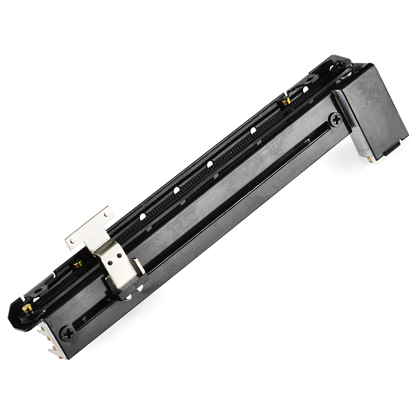
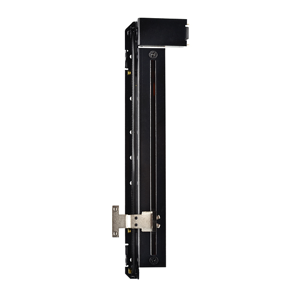
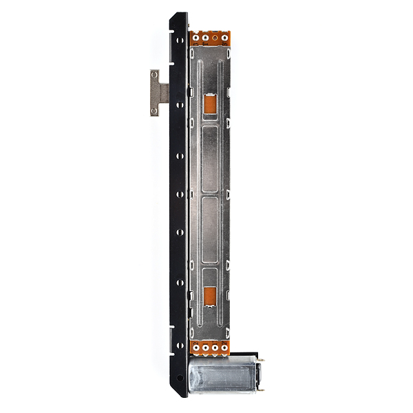
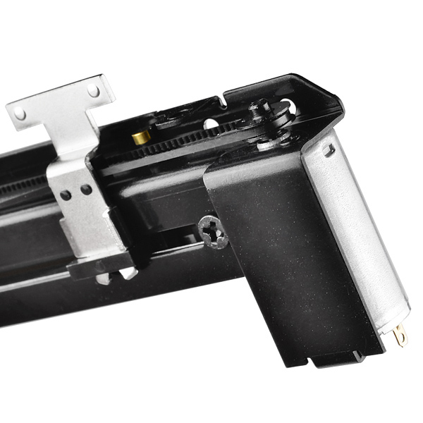
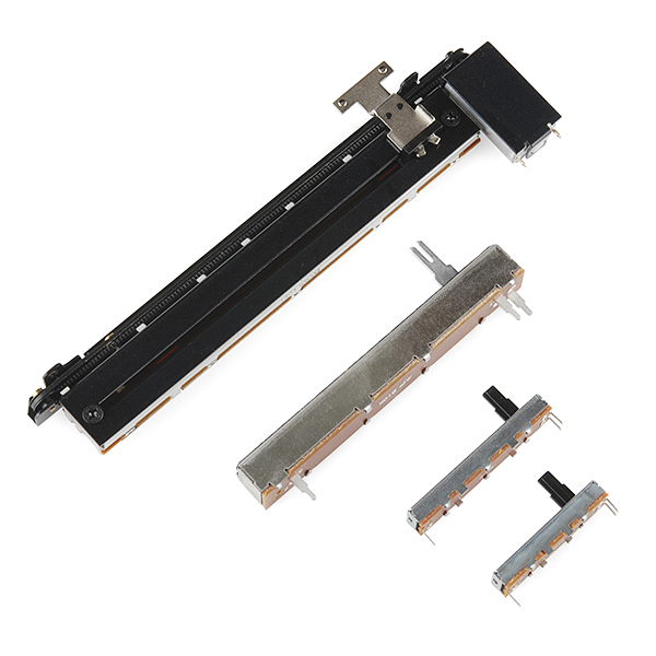
These motorized sliders are very cool. Each is essentially a standard slide pot which is belt-driven by a small motor. The slide contains two separate 10k audio taper potentiometers so that you can use one as servo-feedback in order to read the position of the slider and use the other to control whatever your target is. There is also a touch sense line which is electrically connected directly to the metal slider tab so that you can interface the slider with capacitive touch circuitry.
Motorized potentiometers are useful when you need the ability to jump to preset positions or when you want physical feedback from virtual controllers. There are also a variety of unconventional uses for these potentiometers such as pulsing the motor to provide haptic feedback or just using it as a linear actuator for super light-duty robotics.
Check the related items for plastic knobs that fit these sliders.
Note: We have recently uncovered the correct datasheet for this part and, as many of you had already suspected, this is not a linear potentiometer. This is an audio taper pot with a "15A" profile, you can see a chart of this taper below.
Slide Pot - Motorized (10k Audio Taper) Product Help and Resources
Core Skill: Soldering
This skill defines how difficult the soldering is on a particular product. It might be a couple simple solder joints, or require special reflow tools.
Skill Level: Noob - Some basic soldering is required, but it is limited to a just a few pins, basic through-hole soldering, and couple (if any) polarized components. A basic soldering iron is all you should need.
See all skill levels
Comments
Looking for answers to technical questions?
We welcome your comments and suggestions below. However, if you are looking for solutions to technical questions please see our Technical Assistance page.
Customer Reviews
No reviews yet.
-------------------- Tech Support Tips/Troubleshooting/Common Issues --------------------
In the demo video [ https://www.youtube.com/watch?v=E2Stni6W7Vc ] used a motor driver [ like the recommended motor driver TB6612FNG – https://www.sparkfun.com/products/9457 ] and Arduino microcontroller to move the motorized slide potentiometer. Unfortunately, they did not provide the demo code from the video. There should at least be an example code on using a motor driver with the TB6612FNG’s product page.
Try looking at this comment though => https://www.sparkfun.com/products/10976#comment-53d36766ce395ff8478b4568 . A customer was able to get it working similar to the demo. The code does not seem to be exactly like the demo code but it is a start.
Wonder if these can be made accurate enough for a 3D printer...
While the demo is really fun, it's not very appropriate for this kind of use. If you look at the datasheet, it says expected life is only 30000 cycles. At maximum speed (20mm/0.1sec), it's total lifespan would only be 9 hours, and that's without driving anything except the knob. Load it, and life expectancy will go down.
A timing belt + stepper + controller would be more precise and last longer for only twice the price.
3D printers need a lot more torque than this can probably provide, but it might work for a small pick-n-place...
nope. these have very little torque and wouldn't be good for anything precise like pick and place.
i would love to see a Linear actuator which looks like a pneumatic cilinder and has a fair price (not too high).
Doubt it, because they aren't very strong... I know it doesn't take a whole lot, but still, these are fairly weak. I've seen them on audio mixing boards, and they're easily held back. Fun to play with though!
my thoughts exactly...
Got this working:
Photo of wiring: https://www.flickr.com/photos/lateplate/15068862612/ Arduino code: https://gist.github.com/chrisallick/49e80ea6c82eb1d9ae9d
I can post more details if anyone wants :)
Wow, good job, what is that CHIP you use to drive the Motor? Or you got any schematics where we can see how you hooked it up?
Anyone else find that the potentiometers are not actually linear? I've found the 500ohm is about 1/4 of the way from the far end.
They are definitely not linear.
Measuring between pins 1 and 2 and eyeballing the distance:
0%: 0ohm
25%: 200ohm
50%: 1.1Kohm
75%: 3Kohm
100%: 9.8Kohm
Yeah...very disappointed. Spent 80 bucks on four + shipping when I could have got something very similar in India for 20 bucks total. I specifically bought these since they were 'linear'.
I can also confirm that the potentiometer is not linear.
Please Sparkfun correct this in the description above.
Please can a datasheet with labelled pins be posted for this or [the linear taper version] (http://www.sparkfun.com/products/10976)? The one on the dimensional drawing is okay, but frustrating because it's in a different layout to the actual pot, so can easily lead to mistakes. Many folks have requested this, some even several years ago.
Hello my friends. How are you? We bought 2 of these potentiometers, but is difficult to find a simplified documentation, which prove it a simple example of using this component with the arduino.
that add value to the product and increase demand for the same.
my email is: marciop07@hotmail.com
Thank you very much!
sigh does anyone have a photo of how to wire this?
These won't work for stereo audio, correct? You would need two of them, right?
Wish I could find a stereo motorized slide pot...
Can it be steered directly by software, not manually from the pots?
There are some useful suggestions for use, along with a link to a working project on the page for the linearly tapered version of this product: https://www.sparkfun.com/products/10976
Could two of these be controlled by a slide potentiometer? I got the idea when I saw the video that is below the item description.
Where is the ruler or length measuring on the picture? I need to know exactly how long it is!
Can you please share a code snippet of how you guys positioned the knobs? PID? direct?
In a typical micro-controller ADC setup, I found this formula to give fairly good percentage readings (0..100), you could tweak the 0.36 value if needed.
or for PIC32
It's "Audio Taper" (logarithmic (log) taper), NOT linear!! http://www.maxim-ic.com/glossary/definitions.mvp/term/Audio-Taper/gpk/204
Hi, one quick question...
can the motor of this pot be controlled using a L293D h bridge chip?
thanks,
These are not linear here my measurements:
mm ohm
0 10K
10 8.6K
20 5.5K
30 4.2K
50 1.9K
60 1.1K
80 270
90 100
You guys(Sparkfun) should post how to make that pong device on say instructables. Or even better make a kit out of it!
I'm not a fan of instructables.
But it's pretty simple really. Once you get the mechanical side built (just look at the video), you have an arduino that moves the up and down at a steady pace. it then moves the left/right motor at a slowly increasing pace (incrementing a value for speed through each iteration of the loop). When it reverses direction (by reaching the end of the pot), it compares the value of the pot with the value of the pot on the paddle. if it's within a range, it reverses. if not, it goes out of the loop and starts over.
Little big Q: Do You guys think that the Linear plotter can be used as a pseudo-micromanipulator? What is the smallest increments that the device can make ?
Theoretically near the resolution of the ADC.
What this thing also needs is limit switches so on boot you can have a microcontroller calibrate it.
Primary use and the likely reason these even exist is for physical control interfaces to virtual mixing consoles.
You can see what is likely an entire row of these bad boys at the left-most, closest portion of the following image:
IMAGE!
They're used to ensure changes to virtual versions of the linear pots and the physical versions remain in sync. They'll also move during music playback if you have them automated in software to change.
It's all pretty awesome. A week or two ago, SFE released a product that, when combined, get you almost the rest of a control surface: the ring-o-LEDs here. When you combine that with an rotary encoder, you get a knob who's value can be changed both physically and virtually.
Looks like the curious geeks over at SFE got their hands on an (relatively) expensive control surface, took it apart (as they should have) and said "we need to offer all of this."
I need one!! Or four
Love it!
Jajaja what a crazy project xD