- Home
- Product Categories
- Sensors
- Tilt Compensated Compass Breakout - LSM303DLMTR

Tilt Compensated Compass Breakout - LSM303DLMTR
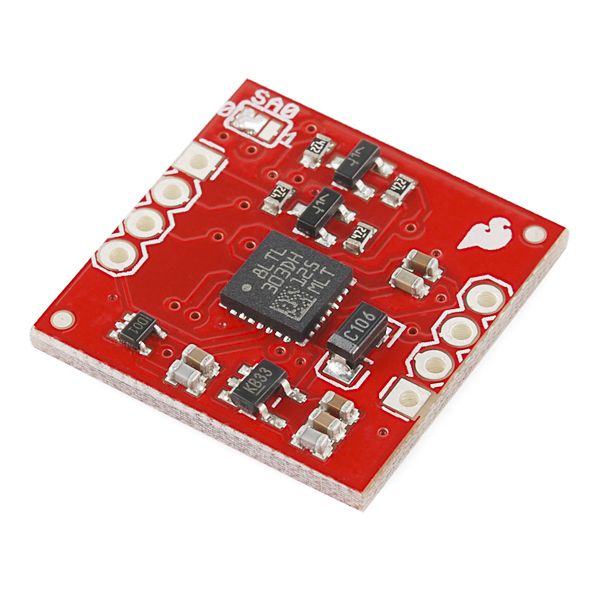
The LSM303DLMTR is a triple axis accelerometer combined with a triple axis magnetic sensor. This arrangement allows for the LSM303 to perform 6D orientation detection. This breakout board uses the LSM303DLMTR to give you all the data you need to feed into a microcontroller and calculate tilt-compensated output!
Replaces:SEN-10703
- +- 2/4/8 g dynamically selectable full-scale
- +-1.3 to +- 8.1 Gauss magnetic field full-scale
- 16-bit data out
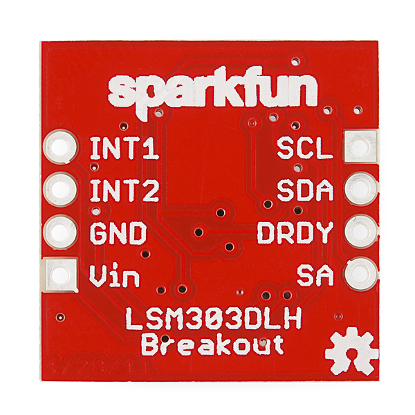
- I2C interface
- Embedded self-test
Tilt Compensated Compass Breakout - LSM303DLMTR Product Help and Resources
Core Skill: Soldering
This skill defines how difficult the soldering is on a particular product. It might be a couple simple solder joints, or require special reflow tools.
Skill Level: Noob - Some basic soldering is required, but it is limited to a just a few pins, basic through-hole soldering, and couple (if any) polarized components. A basic soldering iron is all you should need.
See all skill levels
Core Skill: Programming
If a board needs code or communicates somehow, you're going to need to know how to program or interface with it. The programming skill is all about communication and code.
Skill Level: Competent - The toolchain for programming is a bit more complex and will examples may not be explicitly provided for you. You will be required to have a fundamental knowledge of programming and be required to provide your own code. You may need to modify existing libraries or code to work with your specific hardware. Sensor and hardware interfaces will be SPI or I2C.
See all skill levels
Core Skill: Electrical Prototyping
If it requires power, you need to know how much, what all the pins do, and how to hook it up. You may need to reference datasheets, schematics, and know the ins and outs of electronics.
Skill Level: Noob - You don't need to reference a datasheet, but you will need to know basic power requirements.
See all skill levels
Comments
Looking for answers to technical questions?
We welcome your comments and suggestions below. However, if you are looking for solutions to technical questions please see our Technical Assistance page.
Customer Reviews
No reviews yet.
Took me a bit to find some good references for this board, here's what I found:
Library for Arduino - works great with this module
Video tutorial on calibrating the module - uses the above library
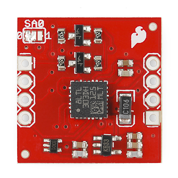
Another note: I'm using this to replace the HMC6352, which is not tilt-compensated. The HMC6352 had a nice north-indicator arrow screenprinted onto the PCB, but this LMS303 board lacks that indicator.... So, to draw it on yourself: hold the board flat in front of you, with the chip on top, and rotate the board until the "SA0" marking is properly readable to you. The north-reference arrow should be drawn to point exactly towards the right-hand edge of the board.
Hope that helps somebody else using this board!
It would be nice if there was a video comparing the LSM303DLH (old one) with this one, especially the issues with noise, which were quite significant even after calibration on the old one, sometimes it could not even get the right world side (eg. pointing it to the south would sometimes result in reading of east). I heard it was caused by the accelerometer, is there any comparsion in the means of specifications?
Maybe you should note in the description this is working on 5v not 3.3v
It's very frustrating when you realize by yourself after purchasing.
I believe that the regulator is a MIC5205 LDO, which from my experience continues to operate down to 3.1 volts... (It stopped working soon after I measured the source Lipo battery at 3.12 volts)
Seems Member #136942 also pointed this out, 2 months ago. I would think that you can still make the board word by bypassing the 3.3V regulator as suggested by them as well.
With the world increasingly moving to 3.3V - if not lower - I do agree it would be nice if all products would have their operating voltage clearly noted, perhaps as the top-most bullet point.
Whew! Found some very nice code at https://github.com/pololu/LSM303/tree/master/LSM303. The first example works well. They also have calibration routines.
No screw holes?! So sad. It could be a great device, but the lack of screw holes makes it needlessly difficult to integrate with one's project.
The lack of screw holes was intentional to keep the size of the board as minimal as possible. This is an argument that occurs for almost every sensor breakout we make as to whether screw holes would add to the board, or if the additional size would be a negative feature. Generally though, a little bit of Velcro can work wonders for applications where you need the sensor mounted.
This man has a very good point! Whats the point of using a tilt compass if you can't keep it from...tilting.
It is worse than I thought, didn't realise it took longer then 9999 micros, infact it takes over 3 ms. Is there something I'm overlooking here?
(edited, correction)
Hi, I'm using the arduino uno v3 with both the LSM303DLMTR and HMC5883L (seperately). With both I've got performance issues. When I readout the LSM303 it's taking over 3 ms to do so.
The rest of my code (not very small), is only taking up 80 microseconds. The high latency is causing problems for serial port communication.
Is this normal?
Any clue as to why this guy was retired? Not only did I get one working straight out of the red box, but it's been a champ. I came back for more, but alas, it looks like it's collecting social security and living in Florida.
The rest of the IMU's / 6 DOF's look like they have some bogus proprietary library nonsense, are a bit pricy, and no one in the comments seems particularly happy with the parts. Any recommendations?
The IC was actually retired by the manufacturer. Though we are working on the new replacement IC currently so there should be a new board coming out soon that's comparable.
After following the great tutorial below, I have this mostly working. But it seems like the Y axis is not working correctly.
I've run this several times to calibrate the MIN and MAX settings. The problem is that Y always reports -4096 for both MIN and MAX values. min: { -4096, -4096, -507} max: { +424, -4096, +518}
As a result, the heading doesn't work correctly. Could this be the module or the library? Has anyone else had this problem?
Thanks in advance
I have a similar issue. When running the calibration code, I always end up with -4096 as my x-min. Does anyone know why this is?
Mine was a bad board/solder. Sparkfun sent a new one and it didn't have the problem. You might want to contact support.
Hello I bought an LSM303DLM digital compass, and have wired it to an Arduino Uno according to the video tutorial below, but I can't see any reading on the Serial Monitor. According to the traces I have put in the program, it keeps waiting unendlessly when the read function is called. Is it possible to make a check to the LSM303 module so that I can see if the module is damaged? Can I do anything else to fix the problem? Thanks
please contact techsupport@sparkfun.com
I have sent an e-mail to that address explaining the problem 24 hours ago and haven't received any reply yet
Our tech support team has been very busy with students returning to school, but they should get back to you by Monday or Tuesday.
Thanks
It doesn't work in magnetometer (bad specification I2C no ACK of chip) same with the level translator It work in accelerometer
hey. crazy question on this. everything i've seen said that having a magnetic field nearby can interfere with the accuracy. What if i wanted to imbed a magnet (say a small/medium rare earth) and use this device to always reference towards that magnet? the furthest the magnet would be is about 30" to 40" from the sensor, would it still detect? How would you determine the size of magnet for distance to override the earth's pole?
I'm looking at using this module with the Raspberry Pi. Since the Rpi uses 3.3v and this module appears to need 5v (based on the 3.3v LDO regulator usage), I'm wondering if I need to worry about this for the i2c interface. I know these are open drain lines, but since this board has pull-ups to VIN, will that cause problems?
I'd rather not use level shifters if at all possible. If the differing levels would be a problem, I'm thinking I could either bypass the 3.3v regulator and power it with the 3.3v from the rpi (thus making VIN now 3.3v). Or, maybe the easiest thing would be to remove the 4.7k pull-ups on this board. Since the Rpi already has pull-ups, would this work?
Does this have level shifters on it so that it is compatible with 5v logic?
Where is the latest updated example code for this board?
Hi Sparkfun Team, Your sample code, in the procedure getAccel, shifts the axis I suppose to make the compass work, but the result is the magnetometer and accelerometer are no longer aligned, at least that is what my measurements show. Additionally the compass works, but only with the chip aligned vertically. Your code even states this in a comment: //rawValues[ZM] = ((int)LSM303_read(OUT_X_L_A) COMMENT --->>> // had to swap those to right the data with the proper axis
I have checked all the register assignment values and they all look correct. What is it about the unit that made you decide to rotate the axis assignments ? Thanks.
Is this pin compatible with the LSM303DLH?
I'm new to all this and was wandering what is the best way to get tilt-compensated output data of this to the PC via USB and what is the update rate? Can I use an Arduino Pico? Thanks again!
I just bought the HMC6352......this one would have helped......