- Home
- Si4735 FM/AM Radio Receiver Breakout

Si4735 FM/AM Radio Receiver Breakout
Replacement: None. The IC is obsolete and we've yet to spin a board for the suggested replacement. This page is for reference only.
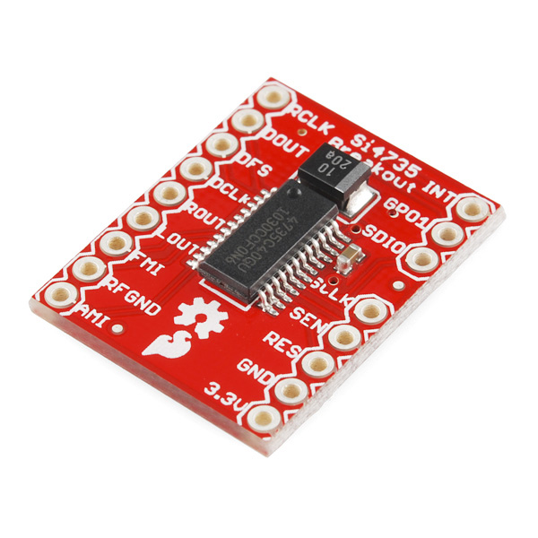
This breakout board makes it easier to use the Si4735 AM/FM Receiver in your next project. The Si4735 is basically a radio on a chip, incorporating complete tuner function from antenna input to audio output.
The Si4735 is a feature-rich solution including advanced seek algorithms, soft mute, auto-calibrated digital tuning, and FM stereo processing. In addition, the Si4735 provides analog or digital audio output and a programmable reference clock. The device supports I2C compatible 2-wire control interface, SPI, and a Si4700/01 backwards-compatible 3-wire control interface.
The Si4735 also incorporates a digital processor for the European Radio Data System (RDS) and the North American Radio Broadcast Data System (RBDS), including all required symbol decoding, block synchronization, error detection, and error correction functions. Using RDS, the Si4735 enables broadcast data such as station identification and song name to be displayed by the user.
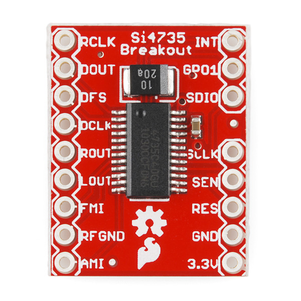
This breakout gives you access to all of the pins you need to make your own radio!
- Worldwide FM band support (64-108 MHz)
- Worldwide AM band support (520-1710 kHz)
- SW band support (2.3-26.1 MHz)
- LW band support (153-279 kHz)
- Digital FM stereo decoder
- RDS/RBDS processor
Comments
Looking for answers to technical questions?
We welcome your comments and suggestions below. However, if you are looking for solutions to technical questions please see our Technical Assistance page.
Customer Reviews
No reviews yet.
I'd sure like to see an update to this board. Not sure what encouragement I might offer to the Sparkfun team, but it would sure be neat.
It's on the list! Hopefully we can get a prototype spun up here soon. Sorry for the delay on this. We had some other revisions that came in at a higher priority.
If I guarantee to buy a bunch will that move this up on the priority? I need a lot of these.
I'll see what we can do.
For those who might be interested, I am releasing my version of the Si4735 library. I have put a great amount of effort into this library and spent over a year intermittently working on it. I believe it to be better then other versions out there. I especially improved RDS and RBDS support.
Project Files
Features and improvements include:
I have included a sample program that lets you control the radio and display RDS/RBDS info with serial port based terminal software such as Putty. This eliminates the need for an LCD.
I have also included advice in the README file on successfully level shifting between 5 and 3.3 Volts and how to correct the many defects in the Arduino shield, including the not well known AM receive bug.
Finally, I have included a document I wrote summarizing everything I have learned about RDS and RBDS. This should be a good place to start for others who want to learn how RDS and RBDS works.
If you worked with previous versions of the library released by Jon Carrier, then you know it would easily crash or malfunction when you started to add more stuff to your program. This is because his library was using most of the available RAM. By storing string constants in flash ROM only, the consumption of RAM by the library has been drastically reduced to about 150 bytes. (Future versions may increase this a little.)
By the way, Jon Carrier's library can trigger the infamous "!!!" bug on the Mega 2560. The bug is triggered whenever a program contains three "!" in a row. All Mega 2560s made to-date have this bug. The symptom is multiple timeout messages when uploading your sketch, but it never gives up. To fix Jon Carrier's library, edit the "Si4735.cpp" file and search for: " !!!ALERT!!! ", and change it to: " ALERT! ALERT! ",
An additional Breakout using the Si 4736/47 to make weather radio available would be a step in the right direction.
I have compared the schematic and the board files with "SSOP Typical Application Schematic" from page 19 of the datasheet of the new SI4735-D60.
I can't see any reason why this pcb can't be used with the new SI4735-D60.
What do you think?
Sure wish you guys would make a replacement breakout board for this with the updated chip or even better one that could tune NOAA weather radio too.
Any ETA on the new one yet?
hi all you are able to read a rds text using this bord? can you send me a correct c code
please help me!!
This document helped me alot RDS Standard, for Radio Text see page 25.
This is the code I came up with and have in my project. Keep in mind, I tried to cut out all the un-related code to reduce the size of this post so a direct cut-and paste of the code may not work, this is intended to at least point you in the right direction. Also, no laughing at any grammar/spelling in my code's comments, I am usually am about three beers in to it by the time I get around to adding comments in my code, which can result in some unpredictable keyboard behavior.
sorry... I had issues with the formatting, above where it says "i&lt8;", I wanted to say "i<8;"
This chip is great! it's FM reception with no antenna out-performs my $300 yamaha with an expensive active antenna! Adding a 3' wire antenna makes it even better. AM reception leaves a bit to be desired, I seem to be picking up noise from the arduino I am using to control it. However I think it has a lot to do with my bread board setup, moving on to a PCB layout may help clean up the EMI being picked up (shorter traces, better grounding scheme.. etc). FYI, for a cheap Ferrite antenna, head over to your local thrift store and find portable am/fm radio to tear apart. I picked up three old radios ($10 total) and scored three ferrite loop antennas all measuring in at 180mH. (plus two cheap headphone amps) Because my end goal is a circuit containing other I2C devices, I opted to use the I2C interface. A “gotcha” that had me hung up for a bit was overlooking tying “SEN” to GND which selects the I2C address. I haven’t spent much time or effort trying to figure out the SW side but have plans to once I get my original project put to bed.
I may well be being an idiot here but I can't get this board to play nicely with my RasPi over i2c - I always get a response with the error bit set high. Do I need to cook up my own external osc? Other i2c devices on the bus are fine (LCD display and a GPIO expander).
check your power up timing, I had the same issue. I was not waiting long enough for the chip to power up before sending commands. the exact times are in the programming guide but if memory serves, it needs a min delay of 110ms for power up. Then after power up, there is a time window for setting reciever properties (am/fm mode, use xtal... etc) that will time out after 100msec. if you send any tune commands inside of this "power up" time frame, you'll get nothing but error bits from then on and need to reset the chip.
I've been able to make this work with ATMEGA 8 and can tune in channels and get back status during the power up process. However if I tune a station and then try to get status (I'm using SPI, 3-wire3) I get the correct status and even station frequency info - but the chip's receiver just stops. Anyone else have the same problem (and hopefully some insight?)
Just a FYI to everyone ... Problem found! I was running the sheild at 3V. I just increased it to 3.3V and everything worked as promised. Interesting that the datasheet says the device can work below 3V but... I also used a transistor inverter/buffer versus a diode drop mechanism to get info back from the chip as the sheild uses a 3.3V supply versus the 5V supply used by the ATMEGA. Works perfectly after I invert the reading I bitbang in. I've already built several systems - no problem.
Did you guys get this to work well without a [ferrite] loopstick?
FM works fine without the ferrite, but it is needed for AM and SW. I got several from some old thrift store specials (+plus some other useful parts). happy hunting
I've have yet to get this to work correctly, but I've learned that this requires a level converter to step down from 5v to 3.3v on the I/O pins. The Si4735 Arduino Shield uses a Hex H2L Level Shifter to do this. I've bought the shield, but, it has too many issues for what I want to do with it, so I'm getting this instead. Sparkfun has an available logic converter: BOB-08745 ($1.95) There is also a quicker/robust converter available: BOB-10403 ($6.95) I'm using the modified (and much more telling) Arduino library of CSDexter which I also recommend. Hopefully I'll get this to work at which point I will share a pin-2-pin description. Until then, maybe Sparkfun could enlighten us? ;)
How do you wire this up, I'm lost
Pretty straight forward, get the data sheet and follow the examples. Get a login, from SI & check out all the application notes, programming guide. Check out SI4735 AM & FM Receiver Shield as an example.
I just got mine in the mail!
On the board it has 3.3 marked for Vcc. The Si4735 data sheet states supply V can be from 2.7 - 5.5V, I/O V is 1.85 - 3.6V.
Have you done this so we don't have to mess around with 2 supply rails?
The chip that your new product is based on is EOL. From their website: "Si4734-35-B20 Data Sheet – Not Recommended for New Designs".
Process Change Notice #1105171 Title: Si4704/05/06/30/31/34/35 to Revision D PCN; Revisions A, B, C End of Life / Last Time Buy, Last Order Date: 23Nov2011 Would not affect this breakout board, as pin functions have not changed.
This thing is sweet.