- Home
- Product Categories
- Sensors
- Venus GPS with SMA Connector

Venus GPS with SMA Connector
Replacement:GPS-11058. We've made some changes to this board, including some additions that make it easy to hook up an external back-up power source and the removal of some unused pin headers. This page is for reference only.
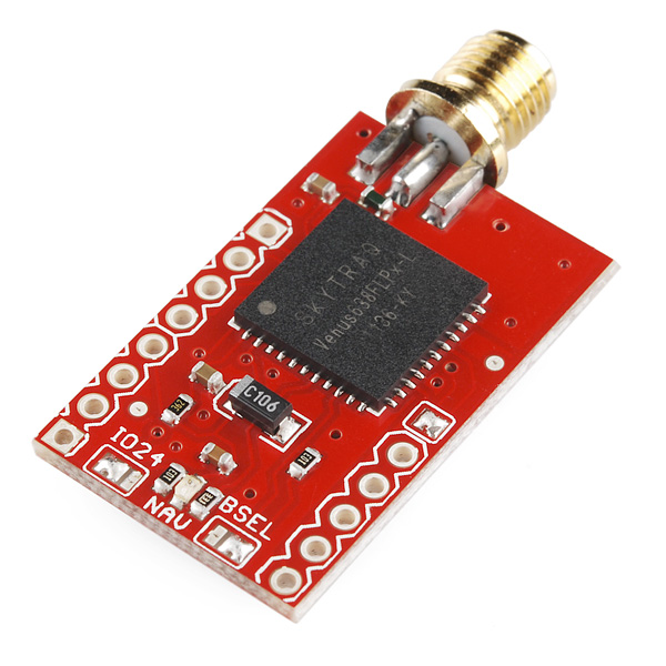
The smallest, most powerful, and most versatile GPS receiver we carry just got more powerful.The Venus638FLPx is the successor to the Venus634LPx and has improved sensitivity and a faster update rate. The new module can be configured to an amazingly powerful 20Hz update rate. With 29mA operating current and high sensitivity, this receiver seriously opens new doors for tracking. Module outputs the standard NMEA-0183 or SkyTraq Binary sentences at a default rate of 9600bps (adjustable to 115200bps).
The Venus638FLPx has improved sensitivity, an integrated LNA (with multipath detection and suppression), built-in RTC, and integrated single power supply making it very simple to use. The Venus638FLPx also allows for limited on-chip logging (check out the firmware below) In addition, the module supports data logging with an external SPI Flash!
Note: The GPIO pins do not serve any functions and can be left floating and ignored.
Replaces:GPS-09133
- 20Hz Update rate
- -148dBm cold start sensitivity
- -165dBm tracking sensitivity
- 29 second cold start TTFF
- 3.5 second TTFF with AGPS
- 1 second hot start
- 2.5m accuracy
- Multipath detection and suppression
- Jamming detection and mitigation
- SBAS (WAAS / EGNOS) support
- 67mW full power navigation
- Works directly with active or passive antenna
- Internal flash for optional 75K point data logging
- Supports external SPI flash memory data logging
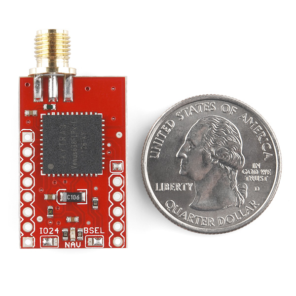
- Complete receiver in 10mm x 10mm x 1.3mm size
- Contains LNA, SAW Filter, TCXO, RTC Xtal, LDO
- Single 2.7-3.3V supply
- 1.15 x 0.7 inches
- Schematic
- Eagle Files
- Venus638FLPx Dataheet
- Binary Command Set
- [GPS Viewer Software](http://cdn.sparkfun.com/datasheets/Sensors/GPS/GPS Viewer - Customer Release.exe)
- Internal Logging Firmware
Comments
Looking for answers to technical questions?
We welcome your comments and suggestions below. However, if you are looking for solutions to technical questions please see our Technical Assistance page.
Customer Reviews
No reviews yet.
It would be great to have this module with an SMA Bulkhead connector such as this one for better attachment to a case.
I'd like to see one with a u.fl connector. That way it can be bulkhead mounted very easily, even mounted slightly away from the sides of the case.
YES! This would make it so much easier to mount this board. It has no holes, so you're left with affixing the main board in such a way that this one sticks through the chassis just right without putting undue stress on the solder joints.
Fully half of Digikey's SMA connectors are bulkhead mounts. It's standard practice. I don't understand why every single one of Sparkfun's connectors are not bulkhead compatible.
In spite of the enthusiasm with which I endorse your comment, I need to minimize the amount of space used outside the enclosure by the antenna (this is for an airplane, where drag is important) so it looks like I'll have to make my own board with a rear mounted antenna anyways.
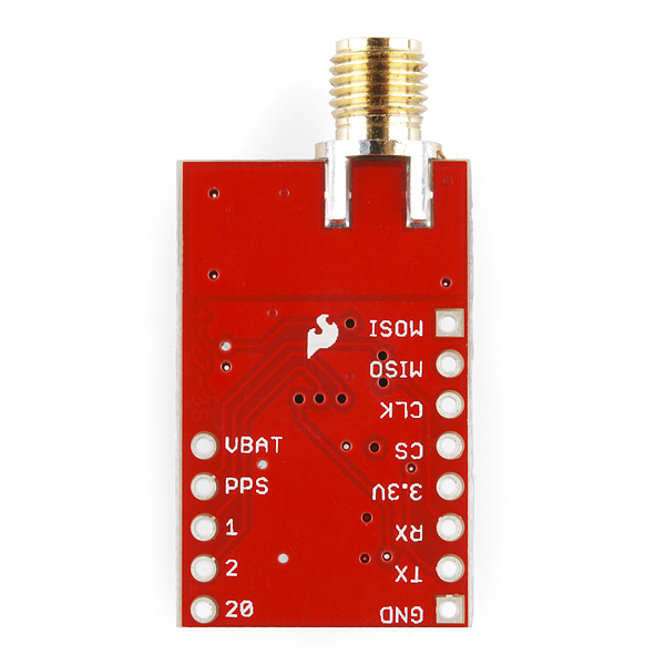
I want to use a 3V coin cell to backup the RAM/RTC- I think that JP4 needs to be left open if I want to do this? I can't see JP4 on the board, although it is shown in the circuit. Can you explain where it is or what I need to to do to connect a backup battery? Many thanks
If you're using this board and not the newer version, the jumper you're looking for is inline with the shorter row of headers. Opening this jumper will allow you to connect a coin cell to the VBAT pin for much faster starts.
Thank you for such a quick reply! I am using this board. I see its been superseded now - but I bought it sometime ago :( I see the jumper now, thank you!
When it will be back in stock ?
Can anyone help a newb trying to get this to work with an Arduino Mega? I have it receiving just fine, but it doesn't want to accept binary commands to modify the frequency of data. I'm trying to pass the data this way:
//Transmit GGA only from GPS Serial3.write((byte)0xA0); Serial3.write((byte)0xA1); Serial3.write((byte)0x00); Serial3.write((byte)0x09); Serial3.write((byte)0x08); Serial3.write((byte)0x15); Serial3.write((byte)0x00); Serial3.write((byte)0x00); Serial3.write((byte)0x00); Serial3.write((byte)0x00); Serial3.write((byte)0x00); Serial3.write((byte)0x00); Serial3.write((byte)0x00); Serial3.write((byte)0x08); Serial3.write((byte)0x0D); Serial3.write((byte)0x0A);
All help is appreciated. Thanks.
I struggled getting this to work reliably (with GPS-00177). I verified that the VBatt pad was soldered to 3.3 on the board. I verified that the high power search jumper was set. I touched up the solder on the center pin. I force fed it ASCII messages to use high power search and to be a pedestrian (not a car) for stationary applications. I confirmed that 1PPS was not floating high during boot. I measured 3.3V on Vcc and on the center pin of the SMA going out to the antenna. I shut down all computations and SD Card writes on my board to reduce possible EMI. Still the unit hardly ever got a fix.
I tried singing: "Venus, goddess of love that you are. Surely the things I ask. Can't be too great a task." No dice.
What worked was getting a ground plane behind the antenna. A 4x4" copper square (I used 3M1181 tape) works great. I tape the four sides of the metal antenna base to the center of the square, since the backing adhesive sticker is probably an insulator. I now get fixes in less than 60 seconds, SNRs ranging from 25 - 55, 8-10 satellites within 5 minutes. I can even get fixes aiming out a window of the house. This is in a heavily wooded lot on the eastern slope of a ridge.
I think the last part of the description here is incorrect. It sais that it has an integrated power supply and external SPI flash, which I don't see in the schematic. Looks like it's just copied from the venus logger.
The text is correct, but may be unclear: this Venus chip has an internal voltage regulator (other variants don't), and, it supports an external SPI flash, which you can connect via the header pins, but is not included on this board (it is included on the logger board).
I don't see how to set the baud rate.
There's a binary command to do so, or you can set it via a menu option in the GPS Viewer Software (link above).
The red LED labled nav has what functionality?
Static == unconected Blinking == receiving gps data
?
That's correct, it will be steady on until the chip gets at least a 2D fix at which point it starts blinking at 0.5Hz.
Now that my Venus638 module has arrived, I've had a chance to try it out and found a few oddities. Top of the list: I can't get it work with the ATMega8U2 breakout board (DEV-10277). It seems to play nicely with the FT232R breakout board (BOB-00718). At least it's working, but it seems odd to me.
The GPS viewer software (listed above) seems liable to crashes, particularly if the virtual serial port link is broken for some reason. It might be that it doesn't like my Vista 64-bit environment. (It wouldn't be the first time!) (EDIT -- rewritten extensively)
Can anyone here help with the Venus binary mode? I'm apparently getting 2 ACKs for commands. When I send a command Venus returns 2 ACKs. First ACK:
This is an ACK for command 00? There is no command 00 that I can find in the book. Then the ACK I expect arrives:
Why 2 ACKs? I must be missing something.
EDIT: Found a forum entry on this very issue. Others are seeing the same thing. 2 ACKs for each command as shown above. sigh.
Perhaps I'm just being dense, but even after reading the device datasheet, I can't see how to set up the module's SPI functionality. If you can get NMEA data or even just position/velocity/time data via SPI, it would ease my system design wonderfully.
It seems pretty clear that the GPS device writes to a memory area, but how do you then get that data? The datasheet mentions being able to set up the logging criteria, but I don't see how you do that.
It sure would be be nice if someone pointed me to the obvious solution I've undoubtedly missed.
Happy Saturnalia everyone!
The SPI port is unfortunately not general-purpose. It is solely to write logging data to an external serial FLASH chip (as we do with the logging version of this board). You might be able to fool the interface into thinking your system is such a device, but I doubt it's straight NMEA data.
The logging feature uses an extension to the binary command set. Some older documentation for the 634 is here: http://www.sparkfun.com/datasheets/GPS/Modules/AN0008_v1.4.11-datalogging.pdf. We'll look for an updated document for the 638 but I suspect that the same commands will work.
Thanks for the reference to the app note on data logging. With just the basic datasheet, I couldn't even figure out how to get log data from the serial Flash memory. I'm hoping the data logging app note will clarify that.
What I'm hoping I can implement is a mailbox system, based on an external SPI-based memory device. At the moment, I'm considering either a dual-port memory system or some kind of arbiter.
You might be able to do this, but given the complexity, it might warrant thinking about coding up a simple serial-to-SPI bridge on a tiny micro, or using a chip like the SCI6IS740 (like we use on the WiFly Shield), and talking to the Venus' serial port instead. Sometimes making your life easier one place makes it really difficult elsewhere. ;)
Another possibility is that Skytraq offers a $200 Software Development Kit for the 638 that lets you alter the existing firmware. The 638 has inactive UART and I2C ports that could be used this way. Contact them if you're interested.
Duh! A serial-to-SPI bridge is vastly easier than the mailbox. The obvious often escapes us! Thanks for the kick in gluteus!
Double Post
which antenna is compatible with this GPS? I need one with a couple of metres at least..
All our GPS antennas are here; you'll need one with a SMA connector to match this board. GPS-00464 has the longest cable of any we carry.
Just to clarify, you guys use the Venus638FLPx-L, not the ...FLPx-D in this break out board, correct?
Yes, we use the L variant (the one with the internal regulator).
I think the Layout Guidelines are outdated.
I wasn't able to track down equivalent documentation for the latest module, however the layout guidelines seem to be mainly about good-practice in layout for RF devices. Because the FLPx-L is specifically designed to "drop in" for the module that the documents reference, they should still apply even though they are, technically, outdated.
The schematics and eagle files are also exactly like the ones for Venus634.
That's because it's the same board ;) being that it's a drop in replacement, we did just that. No new schematic and board files were made because there weren't any changes to the design.
any chance for a reply?
You can leave those unconnected, which is exactly what is done on this board. If you do connect them, you'll likely improve the noise immunity slightly.
interesting. thanks for the reply. that surely simplifies my design. However this is a little odd to me, as there are a bunch of GNDRF, GND and a VCC pins introduced in the new Venus638. can these simply be left unconnected. If yes, then whats the advantage of actually connecting them.