- Home
- Product Categories
- GPS
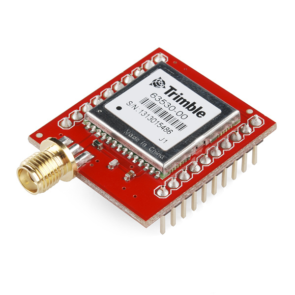
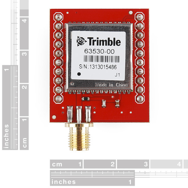
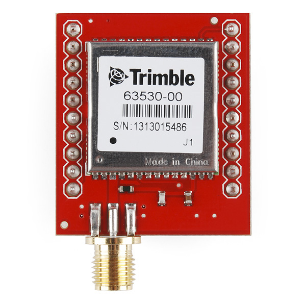
- Copernicus II DIP Module

Copernicus II DIP Module
Replacement:GPS-11067. We no longer solder pin-headers to these boards so that you can decide whether or not you need them. This page is for reference only.
The Copernicus II is a great new GPS module from Trimble, but the SMD module prohibits immediate gratification. This DIP allows the customer to gain direct access to the pins on the SMD module. The Copernicus II DIP breakout has an impedance-matched, end-launch, standard SMA connector that will mate with our SMA GPS antennas listed below.
Check out our GPS buying guide!
- 1.1 x 1.25"
- 0.9" between pins (bread board friendly)
**Replaces: **GPS-08146
Copernicus II DIP Module Product Help and Resources
Copernicus II Hookup Guide
December 18, 2013
A guide for how to get started with the Copernicus II GPS module.
Comments
Looking for answers to technical questions?
We welcome your comments and suggestions below. However, if you are looking for solutions to technical questions please see our Technical Assistance page.
Customer Reviews
No reviews yet.
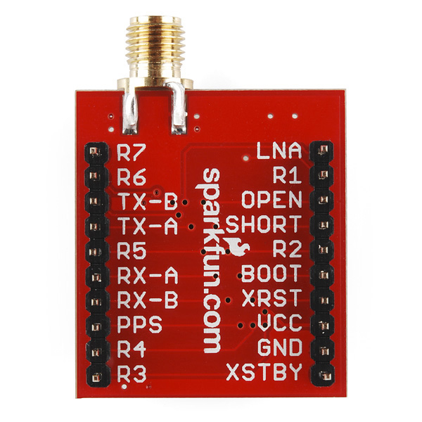
Hi,
As I lost some time while connecting this DIP to my PC, here is the scheme of connections for it (assuming that an antenna such as the "Antenna GPS 3V Magnetic Mount SMA" is used).
My aim was to be able to use "Trimble Studio" on my PC connected to an Arduino on which the DIP was connected.
Thanks a lot Sparkfun's staff for this awesome product!
Hi Joezawaki,
I start writing some TSIP C code to extract raw carrier phase data from an Trimble iQlassen receiver. My code will be released under GPL for GNU/Linux, as soon as i have it running right.
I know, Trimble Copernicus is raw carrier phase capable too.
I am not sure if the enalbe raw data are disabled in iQlassen firmware. As you have an Copernicus, i wonder if you have tested this feature.
Have you done this ?
thx very much,
julio menezes
PS: thx for share your breakout PCB. I set 0x35 message byte3 bit0 to 1, enable raw. i am talking and decoding several messages, all ok but no 0x55 raw data appears.
Thanks for posting this, I've been struggling with getting all the connections right! I presume the >< on the image indicates a pin you leave unconnected?
"0.9" between pins"
Somehow that doesn't sound right.
i also first wondered what it means... it's the distance between the the two rows of pins.
That means it will fit into a cut down 68000 dip socket.
Ah. Got it.
-
-