- Home
- Product Categories
- GPS Boards
- SparkFun GPS Evaluation Board - GP-2106

SparkFun GPS Evaluation Board - GP-2106
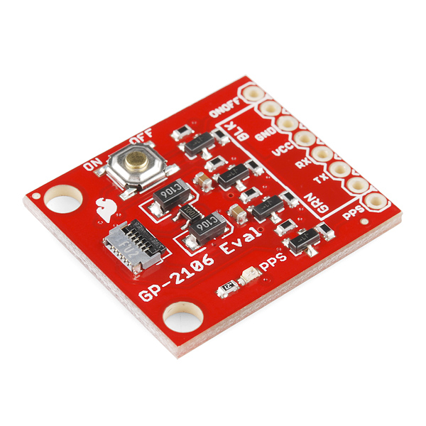
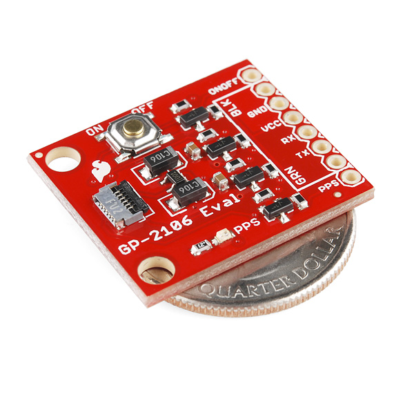
The GP-2106 is a really tiny GPS module. It's so small, in fact, that it's almost too small to use. Not only that, but the 1.8V logic levels aren't compatible with a lot of systems. So we rolled an evaluation board! Don't worry, it's still pretty small.
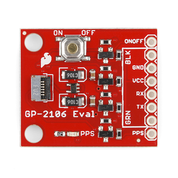
The GP-2106 Evaluation Board features everything you need to get the GP-2106 module talking to your system. Because the GP-2106 is a 1.8V module, we've provided level-shifting for 3.3 and 5V systems. The board also features a PPS status LED, on/off button and an FTDI Basic compatible header!
To turn the board on, you'll have to hold the ON/OFF button for one second. There is also an "ONOFF" pin on the board that you can use to turn the board on in-system by pulling it low for about a second.
This board does not come with the GP-2106 GPS module or the connecting ribbon cable. Both can be found in the related items below.
SparkFun GPS Evaluation Board - GP-2106 Product Help and Resources
Core Skill: Soldering
This skill defines how difficult the soldering is on a particular product. It might be a couple simple solder joints, or require special reflow tools.
Skill Level: Noob - Some basic soldering is required, but it is limited to a just a few pins, basic through-hole soldering, and couple (if any) polarized components. A basic soldering iron is all you should need.
See all skill levels
Core Skill: Programming
If a board needs code or communicates somehow, you're going to need to know how to program or interface with it. The programming skill is all about communication and code.
Skill Level: Rookie - You will need a better fundamental understand of what code is, and how it works. You will be using beginner-level software and development tools like Arduino. You will be dealing directly with code, but numerous examples and libraries are available. Sensors or shields will communicate with serial or TTL.
See all skill levels
Core Skill: Electrical Prototyping
If it requires power, you need to know how much, what all the pins do, and how to hook it up. You may need to reference datasheets, schematics, and know the ins and outs of electronics.
Skill Level: Competent - You will be required to reference a datasheet or schematic to know how to use a component. Your knowledge of a datasheet will only require basic features like power requirements, pinouts, or communications type. Also, you may need a power supply that?s greater than 12V or more than 1A worth of current.
See all skill levels
Comments
Looking for answers to technical questions?
We welcome your comments and suggestions below. However, if you are looking for solutions to technical questions please see our Technical Assistance page.
Customer Reviews
No reviews yet.
The ribbon cable seems loose on the connector. There's no real fit to it, it just falls out. Is this to be expected? If so, what solutions are others using? Hot glue?
I'm not in the office to check, but the ribbon cable connector should have a locking feature. Insert the cable, and try sliding the black and gray parts together. Something should move and lock the cable in place.
Thanks! It's pretty obvious once you know it's there, but a little hard to spot if you don't.
For anyone else, the black tab on the back of the connector rotates. When it's pointed up (90 degree angle with the PCB/connector), the connector is open. Rotate it down so that it's parallel to the PCB and it locks.
Could I possibly get exact dimensions for this board please?
Time to install Eagle :) You can then open the Eagle file(s) and get the dimensions.
That said, I'm all in favor of SFE posting dimensions with their boards, so here's the dimensions in plaintext for ya.
Appreciated.
Those are photos of the contraption i made for the GP2106 & all
https://plus.google.com/u/0/116887879211008829976/posts
i get on the sdcard a confif.txt showing baudrate to be 9600. here .txt looks like : 9600,26,3,0,1,1 baud,escape,esc#,mode,verb,echo log21.txtlooks like :
xÊÊÊxû‡xÊxxÜxfxûòÄxÊ~ûÜxxfx¯xxxÜx‡xx‡Ü‡Ü‡Ü‡Ü‡ÜxÜxx܇܇ÜÊò‡ÜxÜxÜÊò‡Ü‡ÜxxxxffxÄûòÄxÊ~ûòSparkfun support suggeted i get conflictual baudrate between the gps and theOpenLog. Has you can see everythng is compact.
can i change the baudrate of the evaluation board
What is value of resistor connected to led on this evaluation board,
0.27 is shown in schematic, on resistor value is .27,
when I checked with multimeter it showed .4 to .5 ohm
thanks
Should be 0.27 Ohms. Did you measure the resistor out of circuit? It really shouldn't matter though, the only difference would be that the LED would be slightly more dim, and you probably wouldn't even be able to notice it.
hello a1ronzo,
could you show some calculations regarding this?
What is voltage drop across resistor and led?
Thanks
LED FVD: 1.8, FC 20mA, and 1.8V source voltage comes out to a 1 Ohm resistor.
Question: Is there any way to remove on/off button/interface. Right now, to start module I have to press that button on GP- 2106. Is there any work around ? THANKS.
ANSWER: Customer should use its own GPIO to control the On/Off. Then they don't need the button. BR//Jason
could anyone tell me which IC is used to regulate 1.8 v?
I found in schematic
Device: V_REG_LDOSMD2
Name: U2 and 1.8v
Package: SC70
by the way performance of this module is superb, usually it locks within 40 seconds and gives me an accuracy of 1.6 to 2.5 m in open sky conditions,
I am using it as an external bluetooth gps to my android phone.
:D
UPDATE: MIC5366
is there any tutorial, how to interface?
You can plug an FTDI basic (3.3 or 5V) into the header pins, see related items.
Also, you can connect it to something like an Arduino pro mini (but you would need to swap TX and RX connection).
thanks,
I had not connected cable connector properly. Now its working.
performance of GP-2106 is good in open sky,
but takes long duration indoor :(