- Home
- Product Categories
- Addressable
- RGB LED Chain - 20 LED Addressable

RGB LED Chain - 20 LED Addressable
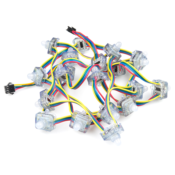
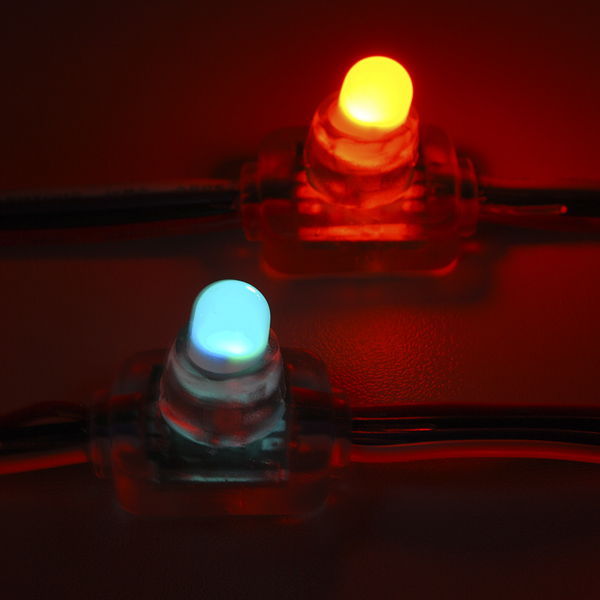
Let there be light(s)! This festive string of addressable RGB LEDs can add color to indoor or outdoor displays. Much like our addressable LED strips, this chain of lights is composed of 20 individually sealed 10mm RGB LEDs and drivers. The driver for this chain is our old friend, the WS-2801 constant current LED driver. The WS2801 is a common, well-supported driver and example code is available for various microcontrollers. The 2-wire control scheme allows you to control the entire chain over only two GPIOs and because data cascades across the drivers, you can chain as many of these together as you can power!
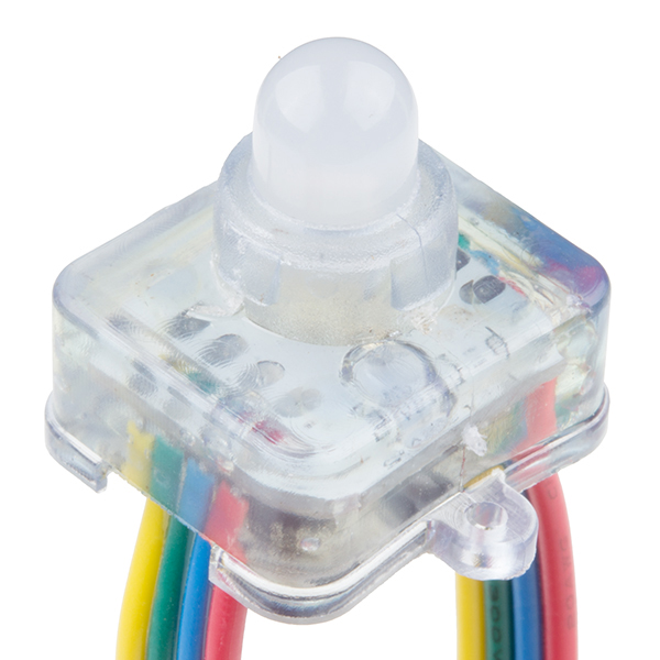
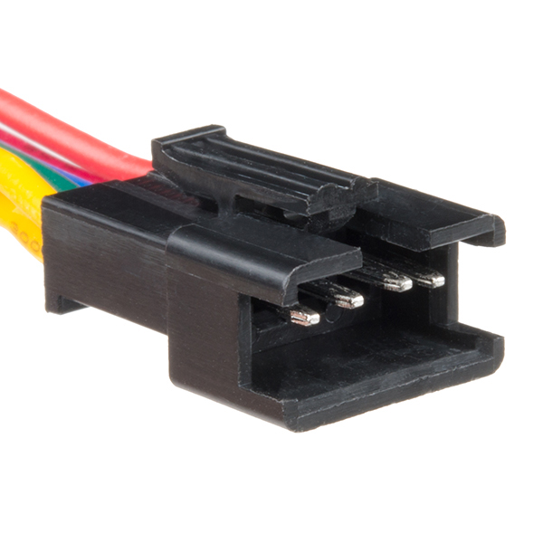
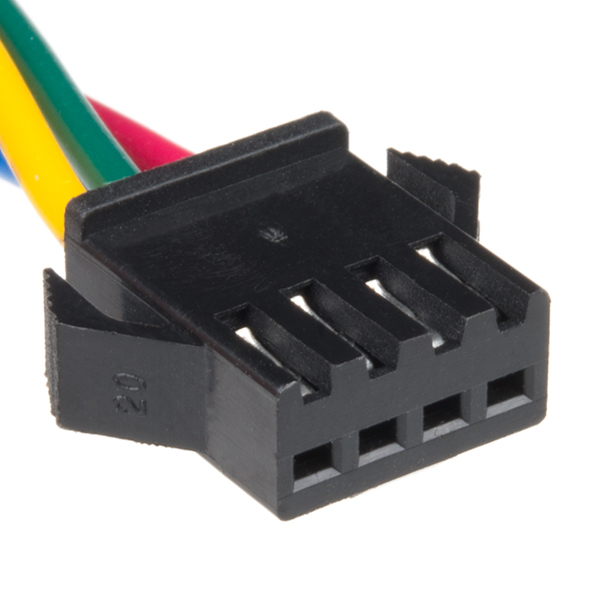
The chain is about 7 feet long with 3" of ribbon cable between each light. It's terminated on either side with a locking 3-pin connector, one male and one female, for ground, data and clock connections. The ground and power are also broken out to bare wire leads on either end. The LEDs mount snugly into a 7/16" hole.
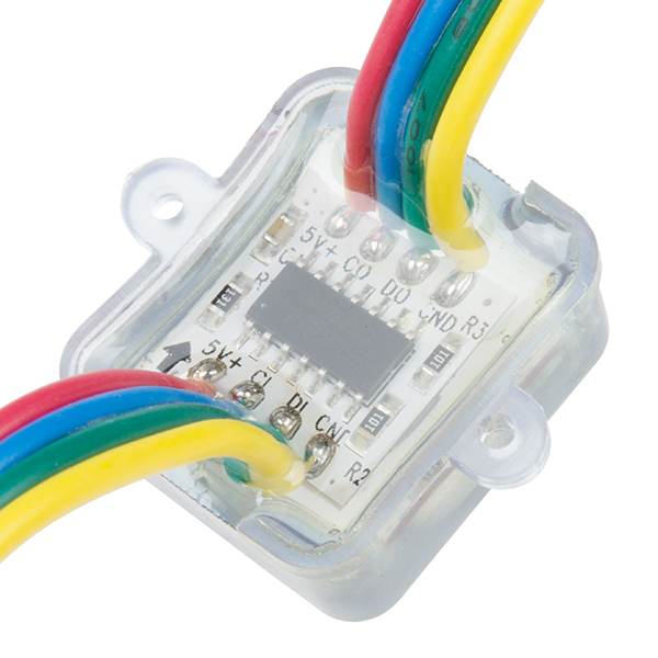
Note: There are no labels on the wires. You can look at the example code or hook it up as follows: clock - blue, data - green, red - VCC, yellow - GND. There is a black arrow on the underside of the LEDs which indicates the direction of the strand. Also, the datasheet below indicates these chains to contain 32 LEDs per meter, this is incorrect. Each chain holds about 10 LEDs per meter.
- IP66
- Rated Voltage 5VDC
- WS2801 IC
- 20 LEDs per chain
- 7' long, about 4" between centers
- [Datasheet](http://cdn.sparkfun.com/datasheets/Components/LED/WS2801 LED pixel.pdf) (WS2801)
- Arduino Library
RGB LED Chain - 20 LED Addressable Product Help and Resources
Core Skill: Programming
If a board needs code or communicates somehow, you're going to need to know how to program or interface with it. The programming skill is all about communication and code.
Skill Level: Noob - Programming will be limited to basic drag and drop interfaces like ModKit or Scratch. You won't be writing code, but you will still need to understand some basics of interfacing with hardware. If you?re just using a sensor, it's output is analog.
See all skill levels
Core Skill: Electrical Prototyping
If it requires power, you need to know how much, what all the pins do, and how to hook it up. You may need to reference datasheets, schematics, and know the ins and outs of electronics.
Skill Level: Competent - You will be required to reference a datasheet or schematic to know how to use a component. Your knowledge of a datasheet will only require basic features like power requirements, pinouts, or communications type. Also, you may need a power supply that?s greater than 12V or more than 1A worth of current.
See all skill levels
Comments
Looking for answers to technical questions?
We welcome your comments and suggestions below. However, if you are looking for solutions to technical questions please see our Technical Assistance page.
Customer Reviews
4.5 out of 5
Based on 2 ratings:
These things are great
I have bought a couple of these and I have used them for Halloween, Christmas and Valentine's day displays. Be sure to get some connectors if you want to use the Arduino for something else. Very easy to program and kids love to have input on changes easily made to the colors and timing
Nice Item
These work, and they work well. Setup is fairly easy and the strands chained together well. The code was pretty straightforward to implement and I got the lights flashing without too much trouble.
Bought this with high hopes for the holiday season. Visions of wowing the family with my cool new Christmas tree lights. Sadly, i cannot seem to get the code to drive the lights correctly. I downloaded the WS2801 Processing code (which appears to be Adafruit's) and plugged it into my Arduino.
The lights work technically in that they do shine and flash and change color, but they seem pretty spastic and out of control (random colors flashing on random lights, with a bias towards the red color) and the patterns have little to do with the obvious intent of routines labeled with names like "rainbow".
Has anyone successfully used the Adafruit code in the link above on these lights?
Thanks much for your help! :)
Just got a strand of these in to try them out. They're cheaper than bliptronics, so my expectations were a bit low. I was pleasantly surprised. They're bright, show great color and appear to be well constructed. They fit in a 1/2" hole and have a little barb around the edge of the light to help hold them in the hole. I didn't think to order a 3-pin connector, but I just cut the connector off the trailing end to use instead. Anyone buying these should also buy a female barrel connector for the power. The Arduino-fed power is plenty for 1 strip of lights. You'll want dedicated power for multiples. I was able to get the sample arduino library programmed and working in about 20 minutes. The only slow down was the sample library has the i2c pins on 2/3, where I'd been used to using 0/1. I moved the pins over and voila. My next step is to integrate a spectrum analyzer shield.
Do you sell just the connectors?
Yes, I'm interested in the connectors too!
Holy crap! Well, it's too late for Christmas this year, but it looks like next year will be even more merry than this one.
I see Ambilight clones in the future...
I set up a test with 6 or seven of these in a long chain. What I found was that the more lights in the chain, the slower the chain was able to update. Does that make any sense? I used the example code to do a color wipe inside the loop(). In a short chain of 20-40 led's it works fine, but in a long strip of 150 lights it updates too slow. I don't understand why it wouldn't just update at 1ms regardless of the number of lights.
That depends on the chip and the driver you're using. I code for the Propeller which allows me to devote a processor to constant updates (typically every 3 to 5ms) and have a RAM buffer for 170 LEDs (or more - 170x3 fits into DMX universe).
These videos show Propeller-based projects I designed and coded for Steve Wang (he created the Predator and a lot of other cool movie monsters): -- http://www.youtube.com/watch?v=YuSMKciw0J8 -- http://www.youtube.com/watch?feature=player_detailpage&v=pO5P7-LxzTE (see Wes Borland's costume at 5:20 mark)
LEDs actually do not fit in a 7/16" hole. They will however fit in a 12mm hole (see datasheet). I cut a giant array of 7/16" holes on a drill press and had to ditch the whole thing.
I purchased similar from Adafruit. Instructions were good. and the libraries they supplied worked great.
I'm still a bit confused. Does sparkfun sell them or must I got to Adafruit/Newark for these ?
Wire color does not match ANYTHING on this website.
From the input side and going left->right my wire colors are Red, Yellow, Green, Blue.
If anyone received the LEDs and the color is Red/Yellow/Green/Blue from Left->Right on the input side this is what the pinout is:
Red - VCC, Yellow - GND, Green - Data, Blue - Clock
Not even close to this product description.
Can anyone tell me if I can run these "directly" from a computer...perhaps using something like this FTDI cable: http://www.sparkfun.com/products/9718 ? Or will I have to use some sort of arduino middle man?
Thanks smart people!
Sincerely, ee noob
Hi EE Noob, These lights use an 'i2c' (read "i-squared c") or "2-wire" (clock and data) interface, which is actually 4 wires (clock,data,power,ground). You need something that will translate serial into i2c commands. An arduino seems like the standard Sparkfun tinkerers approach, but a quick google of 'usb i2c' shows a cool little board that lets you control i2c directly from a program on the computer.
Hey, Sparkfun guys, you should carry these! http://www.robot-electronics.co.uk/acatalog/USB_I2C.html
Grody is correct; the WS2801 uses a clock and data line -- it is SPI without an external chip select. The chip select is handled internally by monitoring the state of th clock line (when it's quiet for a specific period, the chip resets itself to accept incoming data).
Propeller uses that tried my original driver found that some products reversed the red and blue LEDs, hence I added that feature to my driver.
These lights use a protocol more similar to SPI than I2C. They're basically shift registers, only instead of 24 outputs, you need to shift out three bytes of eight bits each, each byte representing the brightness of green, red, and blue (or is it RGB? I forget). Just like regular shift registers, any bytes beyond what a single register can handle will be passed on to the next light in the chain.
Received mine last week, just got time to sit down with it.. My color don't match anything mentioned on this page. Mine wires are Blue/Red/Yellow/Green.. Like others I have a three pin connector.. Can't fined any other notes on this item, feel a little ripped off with this product. Think I'll stick with the blinkm..
Check out this project my freinds and I did with 100 of these LEDs. We used them to make a LED screen that reacts to music.
http://www.youtube.com/watch?v=0CR312-e-nI
can you cut off the waterproof coating? i want to make the the wires between them longer with out cutting and heat shinking on each end.
If I wanted to drive a bunch of these with an Arduino, I'd need to use another power source because of the current. But if I used another power supply with constant voltage, I would be able to control the brightness and color of the LEDs separately through the clock and data wires, right?
Does anyone know how to determine which wires connecting the LEDs are for 5v, ground, clock, and data?
Got mine today. Cable colors match description, but I checked anyways on the little PCBs, all seemed fine. I wired everything up as indicated, used pin 4 and 5 as clock and data using adafruits driver.
When I connect 5V the first LED works (blueish color). When I connect the arduino, nothing changes, all LEDs stay off. Whenever I remove one of the cables from the arduino pins, the LED goes through a series of colors and then stops on an apparently random one. Same happens when I touch the cable (without disconnecting it).
Does anyone have a clue what's going on?
BTW, do I have to terminate them? What do they mean by "direction"? The product description is rather vague. In the description of the other WS2801 LED strips they say "Please see example code for termination explanation." but there's nothing in there!?
Having the exact same problem here.. have you solved it ?
me too !
Did you follow this:
Note: There are no labels on the wires. You can look at the example code or hook it up as follows: clock - blue, data - green, red - VCC, yellow - GND. There is a black arrow on the underside of the LEDs which indicates the direction of the strand.
Has anyone measured the total current drawn by one strand of these lights, all on? Trying to get an idea of the power requirements. Thanks.
I don't remember exactly, but it couldn't have been much more than 1/4 Amp (running the demo software), or my power supply current limit would have kicked in. So that gives you an order of magnitude answer... They were also brighter than I expected. A quick google shows this web page: http://www.aliexpress.com/product-fm/516056341-WS-2801-IC-rgb-LED-pixel-light-12mm-wholesalers.html Which implies 60mA per LED; that would be 1.2A for all of them all on.
Well, looking under a magnifying glass I can just make out on the top of the PCB "SJ-1515ICRGB" and googling turns up: http://www.made-in-china.com/showroom/gernerous11/product-detailObpJKswAASRm/China-RGB-LED-Pixel-Light-WS2801-.html Hopefully the pinout is the same...
I just picked mine up, only to find out that there isn't even a pinout for this product... There are 4 wires between LEDs (Red, Green Blue White) but 3 pin connectors on each end. To make things more confusing, the white wire "T"s to the connector and just a bare wire on each end. Any thoughts?
Looks like mini Cheerlights to me! Just add Twitter
The readme in the example code has a link to adafruit
The connector adafruit sells is a 4-pin version, which is nice for a small number of strings; Newark has the 3-pin plug and the 3-pin receptacle.
Should one infer that since you reference a non-Sparkfun site, that Sparkfun doesn't sell connectors that fit this product?
IP66 - Dust Tight, waterproof versus "Test duration: at least 3 minutes Water volume: 100 litres per minute Pressure: 100 kN/m² at distance of 3m"
Not bad. might be worth submerged testing for table top fountains or such :)