- Home
- Product Categories
- GPS Boards
- SparkFun Venus GPS with SMA Connector

SparkFun Venus GPS with SMA Connector
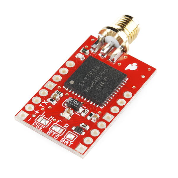
This is the latest version of our Venus GPS board; the smallest, most powerful, and most versatile GPS receiver we carry. It's based on the Venus638FLPx, the successor to the Venus634LPx. The Venus638FLPx outputs standard NMEA-0183 or SkyTraq Binary sentences at a default rate of 9600bps (adjustable to 115200bps), with update rates up to 20Hz! The Venus638FLPx also allows for limited on-chip logging (check out the firmware below), as well as external logging using a SPI flash memory chip (not included).
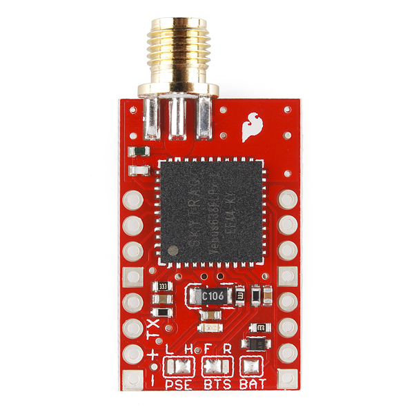
This board includes a SMA connector to attach an external antenna, headers for 3.3V serial data, NAV (lock) indication, Pulse-Per-Second output, and external Flash support. We've also provided solder jumpers to easily configure the power consumption, boot memory, and backup supply. This board requires a regulated 3.3V supply to operate; at full power the board uses up to 90mA, at reduced power it requires up to 60mA.
We've made it easy to connect an external battery or super capacitor to the board, to support very fast restarts after power is removed.
Not sure which GPS module is right for you? Check out our GPS Buying Guide!
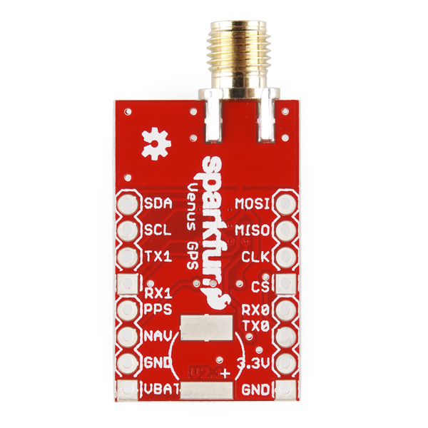
Note: We've broken out the pins for the Venus638FLPx's second serial port (RX1,TX1) and I2C interface (SDA,SCL). However, these ports are not used by the stock firmware. SkyTraq offers an SDK allowing the creation of customized firmware; contact them for details.
- Up to 20Hz update rate
- -148dBm cold start sensitivity
- -165dBm tracking sensitivity
- 29 second cold start TTFF
- 3.5 second TTFF with AGPS
- 1 second hot start
- 2.5m accuracy
- Multipath detection and suppression
- Jamming detection and mitigation
- SBAS (WAAS / EGNOS) support
- 67mW full power navigation
- Works directly with active or passive antenna
- Internal flash for optional 75K point data logging
- Supports external SPI flash memory data logging
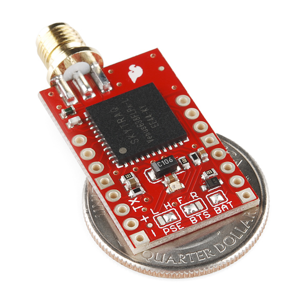
- Complete receiver in 10mm x 10mm x 1.3mm size
- Contains LNA, SAW Filter, TCXO, RTC Xtal, LDO
- Single 2.7-3.3V supply
- Dimensions: 1.15 x 0.7 inches
- Schematic
- Eagle Files
- Venus638FLPx Datasheet
- Binary Command Set
- Logging application note
- GPS Viewer / Configuration Software
- Stock firmware - standard version
- Stock firmware - "high dynamic range" version for sharply-turning vehicles
- Stock firmware- Internal Logging version
- Tutorial (Simon Monk)
- GitHub
SparkFun Venus GPS with SMA Connector Product Help and Resources
GPS giving you the wrong location?
Some customers have been found to confuse the indication given by the sensor thinking that it was in “decimal degrees” but it is in “degrees decimal minutes” notation. This mistake gives a perfect 40Km offset in the interpretation of the position. So the sensor works well, the mistake was in the interpretation of the given data.
Core Skill: Soldering
This skill defines how difficult the soldering is on a particular product. It might be a couple simple solder joints, or require special reflow tools.
Skill Level: Noob - Some basic soldering is required, but it is limited to a just a few pins, basic through-hole soldering, and couple (if any) polarized components. A basic soldering iron is all you should need.
See all skill levels
Core Skill: Programming
If a board needs code or communicates somehow, you're going to need to know how to program or interface with it. The programming skill is all about communication and code.
Skill Level: Rookie - You will need a better fundamental understand of what code is, and how it works. You will be using beginner-level software and development tools like Arduino. You will be dealing directly with code, but numerous examples and libraries are available. Sensors or shields will communicate with serial or TTL.
See all skill levels
Core Skill: Electrical Prototyping
If it requires power, you need to know how much, what all the pins do, and how to hook it up. You may need to reference datasheets, schematics, and know the ins and outs of electronics.
Skill Level: Competent - You will be required to reference a datasheet or schematic to know how to use a component. Your knowledge of a datasheet will only require basic features like power requirements, pinouts, or communications type. Also, you may need a power supply that?s greater than 12V or more than 1A worth of current.
See all skill levels
Comments
Looking for answers to technical questions?
We welcome your comments and suggestions below. However, if you are looking for solutions to technical questions please see our Technical Assistance page.
Customer Reviews
4.1 out of 5
Based on 16 ratings:
2 of 2 found this helpful:
Great board.
Works as expected. Receiving data just fine. One worry though is that $GPGGA message has max altitude up to 17'999 meters but chip spec says it works fine above this altitude. Will report back when I test it at higher altitude.
2 of 2 found this helpful:
Very good GPS
It is one of the better exterrnal antenna GPS's I have worked with. The quick lockup is always enjoyed, although I found it varies allot by which external attenna you use. The best todate was the "Antenna GPS 3V Magnetic Mount SMA". This chip once locked really does a nice job of staying locked even when the location is to area it might not lock up in, or take an exceeding long time.
1 of 1 found this helpful:
Single Serial Output Only
There is NO firmware available for I2C or the second serial port. SkyTraq's SDK is $199 if you want to attempt to write your own firmware to utilize these hardware features. Picked this up with the intention of using I2C due to a pre-existing bus in the project, but SkyTraq customer service dissuaded me and directed me to their Venus8 line which they offer on an Arduino-compatible mini development board (why don't you guys sell that?!).
2 of 2 found this helpful:
Product is great. Programming information is poor
I have both the 10920 and the 11058. After a couple of weeks, I got both of these to work beautifully at 2Hz. I really need the higher update rate, but totally confused as to how to code it to get 20Hz. I've tried Serial.write(160 161 00 03 14 10 01 05 13 10) to get 10 Hz, but I get some random figures on the Serial monitor and then it runs fine but stays at 2Hz. I've tried the gps.putc code variant from another forum, but that didn't work either. Many thanks to a French person who provided the decimal values above, but I don't know how to put these into a coherent code statement that gets processed by the GPS. Any help is much appreciated. was
1 of 1 found this helpful:
So far so accurate!
I am building a high altitude balloon and so far the gps data has been spot on.
1 of 1 found this helpful:
It quit working.
I bought this and an antenna in January. I really was beginning to like it but one day I turned it on and it simply will not acquire any satellite info. Serial port works great but that's it.
No I did not kill it. No there isn't a problem with the antenna. No there isn't a problem with the power supply. I never sent a single byte to it so I know I didn't screw up the firmware.
It worked flawlessly for several weeks, then it just didn't anymore. I had laid it out as a component for making boards but I'm a bit nervous about making boards based on it (for now, anyway).
That sounds odd. I would suggest getting in touch with our tech support team. They may be able to help isolate or resolve the issue.
Good
Very good but something missing
We use the module for speed measurements. We would have appreciated some more information of filtering of speed measurement results. Anyway, the module was easy to apply and Eagle files were for good use.
Recommending!
GPS Unit
Excited to try out the Venus GPS. Delivered exactly as shown.
Very nice! Great product.
I put it on my trackuino and it works perfectly. It's going up in a hab payload on eclipse day.
Worked! Easy to hook up.
On November 13, 2016 I launch Venus GPS on a 12lb high powered rocket to 3200 A.G.L. The Venus survived the 12+ Gee takeoff and provided data all the way up and down on the flight. This was the first time I've had real time telemetry on board. I used a Argent Data Systems APRS modem to encode the GPS data and battery status via HAM freq. I placed the Sparkfun active GPS antenna in the top of the nosecone for good sky view. Will be expanding further data collection. Thanks good support and product!
Used in Trackuino 2.2 board.
I used this to construct a Trackuino board. Does exactly what it's supposed to.
Compact and PPS with RasPi makes NTP Server
For navigation there are cheaper alternatives, but this board has PPS. I use it for precision timekeeping for calibrating watches, by way of a local NTP server. It gets local time +-2 microseconds. The PPS is accurate to 60ns, which could discipline an oscillator to 1ppm within a minute.
The suggested antenna works well, and the package is power-thrifty.
The settings/firmware utility seems to be Windows-only; Linux would be nice.
Pictures https://goo.gl/photos/6nzNXkQax6hS5VNA6
Don't expect any support
As a stand alone GPS it seems to work well as advertised and it is customizable within the scope of their embedded arduino implementation.
We do custom product development and were interested in using the Venus. However, we have a policy not to ship arduino in products (in >products< it consumes a lot of space for no real value) and Skytraq is only supporting their embedded arduino implementation.
They will offer you an SDK, but only if you pay up front so they can 'assign the engineer to work on it'.
Not really the kind of answer you can build a product around.
Hi, Sorry about this issue. I wish there was something more, we as Sparkfun could do to help. Best of luck with your product design!
no i2c
I bought this with the intention of using i2c. i2c is not usable at all. My scanner doesn't see it. The data sheet doesn't give any information except which pins its 'supposed' to be. Honestly haven't made use of this thing yet but because I can't use i2c, it's going in the scrap heap. Very disappointed.
Hi - as mentioned on the product page above, the I2C lines are not implemented in the stock firmware. You will need to contact SkyTraq regarding their SDK that enables this feature.
I am trying to use this GPS chip for a long term application where i need very low power usage. I am wondering if anyone has used an external SD card so the chip can start from hot start each time? Or if there is another way to prevent cold start each lock. For reference I need a lock each 5 minutes and I am wondering how I can start from hot start each time.
Was this the point of the super capacitor which is no longer available, and what would be the power usage to replace that capacitor with a battery?
Thanks!
What you're looking for is a backup battery. If a backup battery is attached to the Venus, it will keep the internal clock running with very little power (a coin cell should last for a year or more). Then when the Venus is powered back up, it will quickly do the calculations to determine which satellites are overhead, rather than just listening for all of them as it has to do when cold starting.
To hook up a battery to the Venus, first desolder the "BAT" solder jumper (ensure both sides are disconnected from each other), then connect a battery (1.5V to 6V) to the VBAT and GND headers labeled on the back. This could be a coin cell holder, an AA pack, etc. Once there's a backup battery attached, when the Venus is powered down, the clock will stay running, and when it's powered back up it should lock within a few seconds. Hope this helps, feel free to ask more questions.
Thank you very much Mike!
Do you by any chance know the power draw rate from the battery in mA?
As far as I can read as the data sheet this device can report position even higher than 40 km if I stay bellow Mach 1 speed?
So it will work for a HIgh altitude balloon project?
I started implementing a python library for controlling the Venus6. https://github.com/rudolfbyker/venus6 Pull requests are welcome.
Hello,
I’m currently working on implementing this board into a high altitude balloon for studying the eclipse later this year, and after some testing and stuff I realized I really liked the capabilities of the board, but was annoyed at lotsa libraries size and complexity in use and reading when for the most part, I’m just logging the data to an SD card for analysis later.
So I decided I’d try making my own library for this board. Since the binary commands are relatively simple and can also be read using the configuration software and an arduino to watch the commands being sent, I thought I’d be able to implement a library that can change the settings using functions, which would mean the board could be configured more easily through code in your setup function rather than needing to permanently change settings through the configuration software. I didn’t like the idea of the permanent setting changes because in my experience some setting combinations like 20Hz at 9600 baud would totally mess up the data and make it unreadable, so making sure all saves are temporary prevents this headache that I experienced.
Anyway, it’s a work in progress that I’ll be updating more over the next few days to finish all the features I need and adding more examples and images for wiring since I could see how a newer person could get mixed up at a lot of points with this board. It would be such a shame for the learning curve to prevent a newbie from using such a cool board. Here it is. Check the page every couple days for updates. https://github.com/Darthpbal/Hermes_Gps_Library
This lib works trough a readLine, getLine, printLine kinda workflow. It has a filter so if you wanna record all the GPS data, you can set that to raw, and if you ONLY want GGA or RMC, you can turn on the filter and only get that. And if you don’t wanna record the whole line of GGA, but only the latitude, longitude and altitude, I’ve implemented the same field parser from the tutorial, so you can easily extract a particular field within the GGA sentence since it follows the NMEA standard. I don’t have the stuff for changing the GPS settings itself yet, but like I said. That’s coming soon. And I'll also probably add examples for logging to an sd card as well since I saw that asked somehwere.
http://www.gpsinformation.org/dale/nmea.htm#GGA
https://github.com/Darthpbal/Mercury_Gps_Library
Hope this helps someone.
hello. i received yesterday this module and also bought an active magnetic sma antenna. i get the GPRMC data successfully on arduino + digole i2c screen, and fast signal lock, but i have the following issues: 1. the lat-lon position is somewhat off by 30 kilometers. it is showing steady position, but wrong 2. the time is wrong (-3 hours), should i add 3 hours in general as i am in gmt+2? 3. the data seems to have a delay. the speed for example goes zero after 3-4 seconds after i stop with the car. the other data stabilize also after 4-5 seconds. 4. i read that the lat-long numbers can never go actually to 10-20hz update, you get 20hz data but the numbers change at 1hz, is that true? i am still new to this, i suppose i need to do some serial connection to pc and do some firmware configuration/settings? all i want is fast (10hz+) lat/long updates for a trackday app i am making.
i will answer myself here. i managed to get 20hz updates unpinned, using information from people here (earlier messages). best way: * one use arduino mega with 4 hardware serial ports, tx0 is usb, connect venus to tx1/rx1. * one download a serial pass through program to the arduino (before wiring the tx1/rx1 pins to the venus....), starting with 115200 for tx0, 9600 for tx1. * now on serial monitor 115200 speed you should see the data. * open GPS tool from here, connect to arduino port with 115200 speed, configure to read only 1 NMEA message series (example, GPRMC only 1). * then set serial speed to 115200. * close GPS tool, download a new arduino program this time with both serial speeds 115200. * test with serial monitor, you should get 1hz messages 1 line with 115200 speed. * now open again GPS tool, set update rate to 20hz, done. perhaps it works with all message series as well, i didnt try.
The only data we needed from this board was found in the GGA string. I could not find a way to only return that string. found that using the TinyGPS++ library was the simplest method I could find to pull just that information I needed. Make sure to leave gps.altitude.isUpdated() set to altitude. If you change it to location.isUpdated or time.isUpdated it will throw off your timing because both location and time are updated multiple time in different parts of the NMEA string.
**Great GPS Module BUT ONE Problem***
The Venus GPS board has no carrier to make it easier to integrate. So, I modified an older USB Adapter for XBEE, the XBee Explorer USB WRL-08687. The inside hole pattern is just right for the Venus board. If you turn the module around so that the RF antenna connector is pointed the same way as the USB connector, and move it to the far end of the hole pattern, it works perfect. You get Ground, 3.3V, DOUT (Tx0) and DIN (Rx0) right where you want it. I used (2) 4-pin and (2) 3-pin socket connectors and separated them one hole to isolate RTS and DIO12. That way CTS, RTS and DTR are not connected from the USB chip to the Venus. It works great for USB connectivity.
I received 1 of these in the last "Ding and Dent Production Builds" order. But I did not have enough time to check what is working.
Any plans to update the supercapacitor footprint to something like the DSK-3R3H204T614-H2L?
-------------------- Tech Support Tips/Troubleshooting/Common Issues --------------------
High Altitude Balloon Projects
The Venus GPS is good for High Altitude Balloon projects. It was recommended by one of our engineers that launched a HAB. Under page 3 of the datasheet [ http://cdn.sparkfun.com/datasheets/Sensors/GPS/Venus638FLPx.pdf ], it states that the GPS receiver is able to achieve an altitude higher than 18,000 meters if it is not past a speed of 515m/s. Exceeding both limits at the same time will disable the receiver. This is so that the part cannot be used in a rocket or missile under the CoCom limits [ https://en.wikipedia.org/wiki/CoCom ].
Err..does this absolutely need an external antenna?
Yes, it does not come with any antenna which it will need to receive the GPS signals.
Thanks!
Hello,
I only need the 1pps output for a disciplined oscillator with an external antenna because I do not catch the GPS signal inside the building. Is it possible to simply "put the power" and wait the "pps" signal with this module, or should I add a uC and write some firmware to handle the GPS?
Best regards
After some poking around with this board, I have found some quirks and bugs I'd like to share:
The 20Hz feature is of limited use. With 100ms apart, two packets arrive back to back with absolute zero space between. This means the first in each pair is at least 50ms late. If you configure it for 10Hz, packets are properly spaced 100ms apart. This quirk is true for both NMEA and binary.
GGA is the only message that is sent faster than 1Hz. All other NMEA types are sent at 1Hz, regardless what update rate you configure.
SkyTraq's current document Binary Command Set totally skips the navigational output format, it only handles the binary input config messages. I had to dig long and deep to find an earlier version (1.10) that explains the format of the 0xA8 message. Highly recommended; it's more efficient in that it has all the greatest hits, all wrapped up into one packet.
Some users on the forum has complained about a static looking nav solution, where not even the least significant digit moves in lat/lon. No GPS is that good! It bothered me too, until I found the fix. SkyTraq calls it "pinning", and is the threshold in position and velocity change that must occur before it's reported as such. By default this feature is turned off (message 0x39 turns it on/off). However, the pinning parameters must also be zeroed out, even if the feature is disabled! Bug! Use message 0x3B and set all to zero. Now you will see the normal "random" drift. You may also want to check out message 0x3C and set car or pedestrian dynamics, for optimal filtering.
- Ebbe
Hi may I knows what does the LED display means for the GPS module?
It will be on but not blinking until it gets a good fix, at which point it will begin blinking.
Ever get > 1 HZ update to work for other messages ? I am trying to update vtg faster but no success yet.
Default firmware only has GGA and RMC update rate related to reduce UART bandwidth. VTG has same info as RMC. Others messages are slow changing, has no need to be updated multiple times per second. If must need VTG at set update rate, you'll need to ask SkyTraq for custom firmware.
My understanding is RMC and VTG have sorta the same info, except RMC velocity is in knots and VTG reports in kph. Pehaps it is reading to much into the accuracy in either case but if the application requirment is for .1 kph resolution, you cant get the out of xxx.x knots (RMC).
I did request SkyTraq for custom software which they promptly supplied, I was impressed.
The 20Hz positions are accurate in that the position data corresponds to the location at the specific time given, however the messages will be delayed (sometimes over 200mS) from the PPS output. If you need to correlate some other event, use the PPS. (On my motorcycle logger, I reset a millisecond counter using PPS and mS-stamp the engine messages).
RMC, GLL, GGA, VTG are all sent at the 20Hz or other value but can be throttled with another setting. The satellite status (GSV/GSA) is sent at 1Hz.
I have a preliminary opensource set/get program at github.com/tz1/skytraq which can fetch AGPS, upload it, and set many of the parameters, but it is a work in progress.
What are other settings that might throttle vtg update rate ? I can get >1 hz on rmc, but not vtg.
Just wondering where the 0.2F supercap as stated above in the description is in the related products. Thanks!
I suspect it might have been Super Capacitor - 0.2F/3.3V. That product is, however, retired and SFE does not carry a replacement. However, you can find the part # there to help you find it or an equivalent online.
Hey, for some reason they took the binary navigation output (ID: 0xA8) message out of the Binary Command Set documentation. This message can be found in the version 1.10 of the document on this page: https://www.sparkfun.com/datasheets/GPS/Modules/AN0003_v1.4.14_FlashOnly.pdf (accessed from the GPS-09133 product). Since this is arguable the most important message, it is strange why it would be removed from the documentation. Others may find this very useful, as it was VERY IMPORTANT to me, maybe you (sparkfun) could make a note and provide a link.
Thanks!
Hi folks!! i though this awesome GPS module was retired!, is good to know there's a new, improved product. i have my own (old version), working at 115200bps and 1Hz samplig rate for testing. o wrote a routine that can send commands into the unit. i send a restart command into the module, the module "should" send me back an ACK message, but, i get a completely diferent message from the especified in datasheet (same size of ACK, NACK, but 2 or 3 bytes different). does anybody have made applications like mine, that could help me?
in my opinion, this module is simply awesome and cheap ($60 with shipping to Colombia). i can get 3D fix positions inside my house, away from windows or doors. the only thing you should take care is the antenna. GPS-00177 antenna tends to brake in place where cable gets into the shield. some epoxy fix that "issue".
Hi I have a couple questions that don't seem to be explained here.
1) How is the firmware updated/changed? 2) whats the difference between the firmware versions posted. from what I can guess the standard version will log to SPI still. The internal logging logs to the internal flash. But what does "high dynamic range" really mean in this context? and how do you define a sharply turning vehicle? 3) what is the difference between booting from FLASH and ROM? Is there a different "standard" version that is non-erasable? if so what does the rom firmware do differently?
1) The firmware is updated via the "GPS viewer / configuration software" linked above. Towards the bottom of the window is a "download" area with a "..." button to select the firmware file. Click the blue button to update.
2) From SkyTraq:
"The HiDyn version calculates velocity using a shorter segment of accumulated delta range data from the carrier loop at inverse update rate interval (100ms @ 10Hz for example), reflecting true instantaneous speed, but is more noisy since it is computed from just 100msec of data instead of the full 1sec segment data for 1Hz update rate."
"The PND version calculates velocity from accumulated delta range over past 1 second sliding window at inverse of update rate increment steps (100msec @ 10Hz for ex.), but using full 1 second of accumulated data, giving filtered less noisy speed reading with more lag."
"The inherent noisier velocity property associated with shorted segment of accumulated carrier phase data for HiDyn mode is not a problem for high-speed high-dynamics application, but will be problem for low speed applications. PND version uses full 1 sec of data at inverse of update rate increments, noise level of velocity is same as for 1Hz update rate, but has more lag and not instantaneous as HiDyn version; although not favored for speed racing applications logging data for later speed maneuver analysis, but perfect for PND applications that allows continuous scrolling of map display at higher update rate with less noisy speed readout."
SkyTraq support is very helpful if you need more detailed information about the firmware versions.
3) There are two boot data sections, ROM and FLASH. Normally you would boot from FLASH, but if you make settings that cause you to lose control of the chip, you can boot from ROM and re-set those parameters to known values.
FWIW, I tried the HiDyn version in a high-power rocket in hopes that it would reduce the lag in reporting altitude changes that I was seeing with the standard firmware. If anything, HiDyn had worse lag, and poorer in-lock performance. Not a conclusive test, but a data point.
I'd avoid the Venus for rocket use.
Which one did you go by?
I lost control of my chip but cannot get it to reset. I should just unsolder the left and middle pads in BTS and solder the middle and right pads instead?
I get output, at a seemingly correct rate, but the characters are completely mangled.
Okay I found out that ROM sets baud rate to 4800, instead of the default 9600. However, when setting the baud rate to anything >= 38400 my arduino mega does not report anything. 4800, 9600 and 19200 works fine for some reason. This, however, removes the option of flashing the device as the SkyTraq software automagically and unpreventable sets the baud rate to 115200. Any clues on how to fix this?
Just skip my comments. Apparently there is some subtle bug in the arduino mega. The following two are NOT equivalent (only the former works for some reason).
define baud 38400
Serial.begin(baud)
const int baud 38400 Serial.begin(baud)
It's not a bug in the arduino. ints in avrgcc are 16bits. 38400 in binary is 1001 0110 0000 0000. Note the overflow into the sign bit! So the const int baud really has the decimal value -27136. When you use that to call begin it gets cast to a long but retains the negative value (which is the correct behavior). If you want to use a const instead of a literal value, you can define it as a const long and you should be okay. If you do use a literal value writing it as 38400L is best because you're explicit about the type.
Note that literal values are, by default, interpreted as ints! Here you are lucky with Serial.begin(38400) working at all because the compiler can figure out from context that you meant 38400 to be a long!
nice! Thanks for the quick, accurate info! Honestly, this is why I love sparkfun so much. now if you just had some in stock... ;)
Hi Guys,
I have just GND and 3.3V connected and am getting nothing on the PPS pin. I am waiting for the GPS lock (NAV pin / LED flashing)
Have tried with a 1k pulldown and without.
Serial data from GPS on TX0 / RX0 is working fine.
I have continuity between the solder fillet on pin 40 of the chip and the PPS pin on the header.
I just want to quickly check there is not a firmware setting or something I should try before I get out the flux and try hitting the pin with the soldering iron.
hi there,
i'm writing you to understand something : 1_i need a gps to realize a wearable device, i just bought this one and i would like to be sure about which kind of configuration (in your opinion) i should use for have battery saving and good performances. To be more precise, i will use this for sport activity. 2_i would be grateful if some of you have some arduino sketch (or better an discovery ST program) to drive such GPS. It would be very fast for me to implement and run the GPS 3_the better way to connect it to have the best performance from it and battery savings at the same time.
thank a lot folks
rik
hey !! anyone ?!?!?!
rik
This GPS receiver will use about 100mA while it's acquiring a lock after it's turned on, and about 50mA after that. You can switch to a lower power mode by changing the "PSE" solder jumper from H to L; this turns off some of the channels. The trade is that it will take longer to acquire lock. There aren't many other things you can do to lower power consumption besides keeping the update rate as low as possible. (You can set this in the "GPS viewer / configuration software" linked above.)
For example code take a look at the TinyGPS++ library. It's the most popular and easy-to-use GPS library and like most Arduino libraries it comes with examples that explain how to use it.
Can anyone tell me what the CLK pin does? I am using this just to get the GPS time. Does that pin output time or is it used for something else?
You'll have to retrieve the time via the serial port (TX pin). If you want a pin that pulses once per second after lock, the PPS pin does exactly that.
It's just the serial I/O clock pin - google around for miso / mosi / clk / cs for details on how you'd use it, but it's nothing to do with the GPS timestamp :)
I've upgraded to this GPS module. I do not get the NEMA GLL line. I get the GGA, GSA, GSV, RMC and VTG. I can certainly use the info from the GGA but my code was parsing the GLL when I was using a different GPS. Is there some setting that I am missing to get the unit to output the GLL info?
It's turned off by default but you should be able to turn on the GLL message (and any others you want) using the "GPS Viewer / Configuration Software" linked above. It's in the "Binary / Configure NMEA Output" menu. The Venus will remember the change through reboots.
Where is the ultracap?
Unfortunately that part was discontinued by the manufacturer. However you achieve the same result by connecting any 3.3V-capable supercap between VBAT (cap +) and GND (cap -).
For those wanting to buy this GPS in near sea-level areas, the GPS altitude bottoms out at 27.4 meters. I had a couple dozen of these for an experiment in Florida, and they all reported 27.4m of altitude. Actual altitude was near 5 meters.
Hi I just purchased this GPS module and I can not configure at all. I would like to update it update rate but am unable to. I have been using the standard code found on Simon Monk's site to view GPS messages at 1Hz. But I am unable to use the SkyTrack GPS software for anything other than reading. When I try to update any settings on the Venus chip I get an error saying "Target doesn't replay please power cycle target". Am I missing a serial command so that the software can communicate with the GPS chip? I'm pretty new at using Arduinos, I apologize if this is a simple question.
It sounds like your TX link (from the GPS) is working correctly, but your RX link (to the GPS) is not. You should be able to run a simple serial passthrough sketch like the following, then quit the Arduino IDE and run the SkyTraq software. Connect the GPS TX to Arduino pin 2 and RX to pin 3:
Hi, my Venus GPS don't work very well. It's syncronized with GPS signal because the LED is flashing, but I have any signal on Tx Pin. Do you know what I can do ? Is it dead ?
Thanks.
Can you suggest somewhere to source the Skytraq chip on its own? I'd like to integrate it into a project where size is critical
We have it for sale here.
Thank you!! Not sure how I managed to miss that
Will this work at all without connecting antenna? If no, which antenna is recommended?
Nope - you need an antenna. Check the recommended products tab above. There are two different antennas listed that are compatible with this board.
I watched the AVC2014 today, and it has reinvigorated my DIY project mode. I am now looking at the Venus GPS module to make my own vehicle. My question is, are the commands from the Binary Command Set transmitted to and from the Venus through the UART port? Or is it a combination of UART and one or both of the other two synchronous serial ports?
We're glad you enjoyed the AVC, and look forward to your entry next year! Everything on a stock Venus happens through the single async serial port. The other port hardware is available but unused unless you write custom firmware (a development kit is available from skytraq). Good luck! (Protip: start now.)
Hi,
Does anyone knows what is the current rating for pin 18 or VBAT?
According to the datasheet, "less than 10uA."
I'm having some accuraccy issues. The latitude measurement is off by about 0.02 minutes. Although this is not very wide of a margin, it may not be suitable for some of the applications I had in mind. Has anyone else faced this issue? (EDIT: other weird things are happening now. I left it for about an hour without moving it. At the beginning of that hour, the minutes measurement was 0.0068 less than it is now. Can anyone else relate?)
running 38400 baud. Using SkyTraq trying to increase up date rate, which I can for RMC. However cannot get update > 1 Hz for VTG.
tz states "RMC, GLL, GGA, VTG are all sent at the 20Hz or other value but can be throttled with another setting. "
Please advise what the possibilities for "throttled with another setting" might be.
I see a comment explaining an issue someone was having going to 38400 baud. I wonder if I am having a similar issue only I can make 57600 work but not 115200. When I set to 115200 using the GPS viewer the gps goes to 115200 (as evidenced on a scope) but I cannot ever again establish communication until switch to boot from ROM and start over. Which by the way seems to work (boot from ROM) unpredictablly, but maybe thats just me and not the point.
I am using a software serial port and wonder if going across the 65535 boundery is an issue...or if there are any other ideas.
Here is the test code i use:
We have had issues running Arduino's software serial above 57600. I don't believe it's a 16-bit issue, I think it's just the raw speed required to manually time every sent and received bit. If you need to run at 115200, I recommend using a hardware port if possible.
Hi everybody, I have a little auestion: how can I enable the EGNOS functionality ? In the GPS viewer and configuration software is possible to enable only WAAS, but here in Europe there is EGNOS. May there is a special firmware for the Venus ?
Thanks in advance for your replay,
Alessandro Rossi.
From GPS Viewer, WAAS pull-down menu, select Configure WAAS, set Enable. They had a bad naming, configure WAAS is actually configure SBAS.
I am not aware of any, but you might contact support @ skytraq . com . tw and ask if they have such firmware or if they'd consider writing it. I'm sure many European users would appreciate that capability.
This unit has worked well for me, but it does have a hardware quirk. I have found that if the PPS output line has any kind of load on it, the GPS won't always start. I finally had to tie the PPS line to logic through an NPN transistor, and that seems to have made the PPS reliable. I tried passing the PPS signal through the level converter breakout, but the FETs loaded the line too much and the GPS would fail to boot. Anyway, if you experience random startup issues, you might look at the digital output lines, to see if this is the same issue I encountered.
The PPS output serves as debug mode selection during power on reset. If pulled-high, it'll enter debug mode, behave as frozen. It has internal weak pull-down resistor inside. If connected to some MCU input pin with pull-high resistance, might need a lower value pull-down resistor outside to not enter debug mode.
Hi guys, I bought this GPS reciever a while back and I am going to use it on a formula student race car.
I get it up and running and I am able to recieve GPGGA NMEA data at 1 hz update rate using the TX RX interface. The problem is that I want it to update at 20Hz, and I have tried to configure it using the "Binary Command Set" document. But it doesn`t reply at all, which is a bit troubling.
The command I have tried to use is: Configure Serial Port: A0 A1 00 04 05 00 05 00 05 0D 0A.
Any help would be awesomely appreciated.
Note that when you increase the sample rate, the Venus will immediately and quietly raise its baud rate because it can't get the sentences out fast enough at 4800 or 9600bps. I can't remember immediately what it goes to, but you might try changing your terminal to the higher baud rates (38.4, 56, 115.2). The above "GPS viewer / configuration software" handles this automatically so that would be another good place for a sanity check.
The modules I recently purchased came with firmware version 2012.7.10. I installed the firmware on one module from this page that turned out to be older (2011.10.21). I would rather have both with the latest firmware. Anybody have Venus firmware 2012.7.10 or newer? Thanks!
The binary commands should be the same for this and your other Venus GPS (GPS-10920), right? I've got everything working on the other one, but with this one I can't get the baud to change using the same binary command.
The two boards currently use the same chip so should act the same; is your other board an older model with the 634? For questions about the binary commands you might try contacting Skytraq support at info at skytraq.com.tw.
Nope, same chip, 638. Using the same code. I'll see what I can do with the configuration software.
Hi everyone. I have a question about active antenna. In datasheet is shown that active antenna is hooked up to power supply 3.3V and connected to input pin RFIN pin. I need to use an active antenna with power supply 5V. Is the RFIN pin 5V tolerant?
The Venus will supply 3.3V to an active antenna, and I don't believe the antenna pin is 5V tolerant. If you're going to power your antenna with an external 5V supply, you should be able to use a blocking capacitor as in this circuit to keep the 5V out of the Venus (note the capacitor between the IN and OUT BNC connections). We've talked about this sort of setup for indoor testing of our GPS builds, but we haven't tried it yet.
It does work whit the PRT-00449, i get the NMEA signal in my terminal on the computer but the GPS can't get a fix position. I have tried outside whit clear sky but wont work. I can't connect to GPS Viewer either. I have also coupled the Rx to the PRT-00449 now but that didn't help me to connect to GPS Viewer.
I am using Antenna: Antenna GPS Embedded SMA, GPS-00177
Could that be the problem or what else could be wrong? Need to found out so i can order more whit confidence. /Robin
I have been testing the Venus GPS tonight, I currently have it running. However I was having issues with it for several hours which i tried to figure out what was wrong with it. It would turn on with the LED only turned on very dimly. I eventually figured out that it was because of my bench power supply. My power supply voltage ramps up relatively slowly when the output is enabled. The Venus does not like to be started with a slow supply. If I disconnected it and plugged it back in with the supply turned on the GPS starts fine. It may be a good idea to have a power brownout protection circuit if you install the device in a situation it may experience brownouts.
I have been testing the Venus GPS tonight, I currently have it running. However I was having issues with it for several hours which i tried to figure out what was wrong with it. It would turn on with the LED only turned on very dimly. I eventually figured out that it was because of my bench power supply. My power supply voltage ramps up relatively slowly when the output is enabled. The Venus does not like to be started with a slow supply. If I disconnected it and plugged it back in with the supply turned on the GPS starts fine. It may be a good idea to have a power brownout protection circuit if you install the device in a situation it may experience brownouts.
Hey! I can't get a NMEA signal to my computer out of this. I can see in the oscillator that it gives me a NMEA signal (differential signal).
I am supplying it whit an external 5VDC.
I have tried to change baud-rate and all the other options on computer but none give me an output in the hyper-terminal. The gps gets a fix so no problem there. What can be wrong? Need to know cause need 22 of those for an application.
Best Robin H.
Unless I'm missing something, you don't need both BOB-11189 and PRT-00449. Try hooking the Venus directly to the PRT-00449 and see if that works any better. Power the PRT-00449 with 3.3V since that's what the Venus operates at. Let us know if you have further problems.
Any plans on getting the new Venus 8 with 50Hz update? (And maybe glonass?)
Possibly. Just out of curiosity, what is your application where 50Hz update is more useful than 20Hz update?
High performance vehicle data logging. Also detailed geocoding (if I'm driving at 55mph, that is 88 feet per second so the location of individual frames at 30 or 60fps can benefit from the detail). Having path-dots 3 v.s. 10 feet apart.
I was thinking about using this GPS with "Arduino Uno- R3 SMD". But the 3.3V pin will only support a current of 50mA. That would be to low for this GPS, correct?
The Uno has a dedicated 3.3V regulator that's good up to 150mA. The Venus needs in the vicinity of 100mA when starting up (it will use less after it has an initial fix) so you should be fine.
I'm having trouble sending any commands to my receiver. I am using the FTDI serial converter, and connecting it to the board I can receive all the NMEA messages and see it acquire satellites and such, but whenever I try and send a command (like reset, or query version or whatever) it just hangs for a while then says it timed out. Any ideas?
Anyone have some example C code to send a binary command to the receiver?
Thanks
You obviously have the Venus-to-FTDI link working, double-check the wiring in the other direction to make sure everything's in the right place. A loopback test (connect TX-RX on the FTDI and type a few characters in a terminal program) will also let you know if everything up to that point is working.
It also may or may not be related to your problem, but SparkFun's 3.3V FTDI board can only supply 50mA of current. The Venus requires 100mA when it's starting up. You should use a beefier 3.3V supply to power the Venus.
Just FWIW, Skytrak is putting out a new GPS module with Venus 822 chipset, check out NavSpark on indeigogo. Not clear if it will reach its funding goal though. EDIT: looks like it will happen. Maybe SparkFun can carry this one too.
Skytraq version GPS Viewer 0.4.940. Hi, on your website you're providing Skytraq GPS Viewer 0.4.833, do you have the version 0.4.940 or a newer one? Which are the parameters you need to set up in order to have the most accurate gps positioning down to 1m as described in the tech specs? Thanks in advance for help ;-)
Hi,
So I've been working with the Venus GPS module. I was configuring the pinning and the output and suddenly it stopped locking up to satellites. I then did the factory reset, followed by a reboot on SkyTraq. Now it's outputting gibberish characters and not responding to any queries or anything. When I try to flash the stock firmware it says, "target doesn't reply, please power cycle the target". How do I do that?
Thanks
Gibberish characters usually means that there's a mismatch in baud rates between the Venus and the Configuration Software. Try telling the software to use different baud rates; 4800 and 9600 are common, but if you've increased the sampling rate the Venus will have quietly increased to a higher rate. Hopefully one of those will restore communications, at which point you can command the Venus to whatever baud rate you like.
If nothing restores control of the Venus, you can change the "BTS" jumper from "F" (Flash) to "R" (ROM), which will cause the Venus to boot from a backup copy of the firmware in ROM (likely at 4800 baud). At that point, you can reflash the stock firmware to flash memory, and change the jumper back to "F".
Edit: also, regarding output suddenly stopping, ensure you're using a 3.3V power supply which is strong enough to run the Venus. It requires over 100mA when acquiring satellites. A 3.3V FTDI board will not be able to provide enough power.
These work really great for positioning. I wanted to use it, to get an exact time, but this seems to be impossible. The 1PPS pulse is perfect and very exact, but the binary as well as NMEA timestamps are shifting by up to 1 second. This makes it impossible to assign the exact seconds to a 1PPS pulse. My Logic analyzer shows, that sometimes the timestamp is around 100ms to 500ms late (would be ok I guess), but then it is 500ms to 1000ms earlier, then the actual time. To be precise: After each reboot, the modul seems to have a different time offset to the actual time.
Any help as to how I can assign the exact time to the pulses would be much appreciated. Im currently guessing, that this is not possible with a gps module.
Have you tried turning off the irrelevant messages except for e.g. RMC, and increasing the baud rate?
Thanks, yeah tried this, and also increasing the baud rate. But I found the solution to my problem myself. Obviously, the GPS is only having wrong timestamps for a few minutes. When it gets a 3D position fix, it changes the timestamps to the correct value. This happens usually 2-5 minutes after the 3D fix. During the first few minutes, the timestamp value seems to be in a range of +/- 1 second or so. This is what confused me, sometimes it is ok, sometimes it was 1 second too early. But now it's consitently fine, around 130ms late at 38400 baud. So the only problem was, that I was not patient enought during my initial tests. Thanks!
Glad things worked out, and thanks for posting your experiences; it will help others in the same boat!
Hi, i have connected the Venus GPS to my Arduino UNO, with 3.3v pin to 3.3v power supply, GND to GND and Tx0 pin of Venus GPS to RX pin of my arduino UNO. ( same as the tutorial of Simon Monk). however, this is what i get from the serial monitor : Lat: 0000.0000N Long: 00000.0000E. Anyone know why? do i have to connect 3.3v to VBAT too and maybe a second GND is needed too?
Sounds like there might be something going on with your antenna, or that your Arduino isn't providing enough current to allow the module to get a lock. That' generally the two main culprits when the gps is outputting 0 values in the sentences.
Hi, i connected the Venus GPS to my Arduino UNO, 3.3v to 3.3v,GND to GND and Tx0 from venus to Rx pin of my Arduino UNO.(same as the tutorial from Simon Monk). and i get the following result in my serial monitor : Lat: 0000.0000N Long: 00000.0000E. can anyone tell me why? do i need to connect Vbat to 3.3v and a second GND too?
I'm looking to build a vehicle speed detection application.... will this give 20 speed samples a second? Can someone confirm? Any other choices?
In my lab I have a 5V, 40dB GPS antenna installed. Can I use that as an antenna for the this GPS module? Will I need to make any adjustments to the connections (any circuit elements or circuits I might need to impliment) in order to get it to work? Please help me out...
"There are even pads on the bottom of the board for the 0.2F supercap (not included but you can find it in the related items below),",
This is no longer in whatever is below.
Sorry about that! It looks like we had to stop carrying that particular capacitor. A 0.2F supercap should still work for this, but we'll get the description updated on that.
Does anyone know how to use the Nav Lock indication? Does it simply output 3.3VDV when locked?
Does anyone know where I can find info on the nav lock indicator? Does it simply output 3.3VDC when a lock is acquired?
NAV is the same output that goes to the red LED; it will be steady on if there is power but no lock, and blink at 1Hz when a fix is acquired.
As a request for the future. Do you think you guys could make a breakout for this chip in a PCB Module (exposed pads on the edges of the PCB) type arrangement? To be able to solder a breakout PCB for this chip straight onto my custom board, rather than using pins, would be great!
At that point, your best bet would be to simply use the bare IC, available here. Doing a breakout board with SMD pads to solder it down simply would add the additional cost of a pcb, as well as the additional space required for a whole pcb, which doesn't make much sense for us.
If you really don't want to stand it off with headers (and don't want to start with the bare chip), here are two more ideas: One is that you could carefully saw the edge of the PCB to end up with plated-through half-holes, such as those on some of our Bluetooth modules. You'd have to come up with a matching SMD footprint to solder it down to your board. But frankly what I would do is just use matching header holes on your board, lay them flat against each other, stick headers through both boards kebob-style, and solder them together. To make the final connections you'll need to pull the plastic off the header and cut off the excess. But it will be as low-profile as you can get without putting the components on your board.
Ah ok, very nice ideas there! Yea, the main problem with just going the bare IC is trying to solder that part. In some product pictures, it looks like it has pads on the bottom as well as around the sides? Is that right? I think simply removing the plastic from the headers is the simplest, easiest and cheapest option for me! Thanks again for your ideas.
I'm having a curious problem. I'm trying to connect this guy to a Byonics TinyTrak3 for a HAB project. The tiny track only understands NMEA0183 in RS232 and 5v TTL, so I connected a 5v-3.3v level converter to the GPS. I'm able to connect it through a max232 to a serial port and use the software to configure it. that works perfectly fine, and I get a signal lock and an accurate position in no time. Also, the tiny track seems to be working as well, I can configure it, and it transmits packets with my callsign. After making sure I configured the tiny track to accept TTL signals, I've tried to connect the two. The light on the GPS is blinking, but I see no position info in the transmitted packets. I've quadruple checked all the pinouts, even recreating the connections on a breadboard. I've run out of ideas, maybe this is a better question for Byonics, but I'm not sure which end of it has the problem.
Does Sparkfun have any GPS antenna compatible with this board?
Yes, several are listed in the related products below.
Hi,
is it possible to operate with regulated 3,6V? The Datasheet of the Venus638FLPx says that it is possible but on your webpage you say it ist only safe up to 3.3V.
Thanks, Michael
You can run it on 3.6V if you wish, but be careful as that's right against the upper limit.
Hello, I have one of these about 6 months old. I am using the example tutorial from Simon Monk above. My GPS gets a fix, and the red lights flashes.
My issue is that it seems as though I do not get regular updates without physically touching the unit itself. And when I say touching, I mean I have to actually be putting a little pressure onto the SMA connector, like it has a dodgey connection to the board or something like that. BUT the whole time, the unit itself still has a fix.
I am not sure where to look for ideas? I have connected a set of header pins to the unit, and they are all ok.
Example output here: Lat: 2733.0388S Lat: 2733.0388S Lat: 2733.0388S Lat: 2733.0388S Lat: 2733.0388S Lat: 2733.0388S Lat: 2733.0380S Lat: 2733.0376S Lat: 2733.0367S Lat: 2733.0369S Lat: 2733.0370S Lat: 2733.0375S Lat: 2733.0381S Lat: 2733.0389S Lat: 2733.0390S Lat: 2733.0391S Lat: 2733.0390S Lat: 2733.0393S Lat: 2733.0394S Lat: 2733.0394S Lat: 2733.0394S Lat: 2733.0394S Lat: 2733.0394S
Also further to this, the Direction can report all over the place. Without any rotation, it can go from 17deg to 170deg to 317deg. Is this normal?
This sounds like a grounding issue to me. What connections are you using from your system to the Venus, and how are you powering it?
EDIT: re. the direction, this is normal for all GPS units. There is no internal compass, so it relies on movement and multiple fixes to figure out the direction. If you're not moving, the fix will naturally vary a bit, resulting in "random" direction. You can turn on position pinning to eliminate this if you wish.
Thanks Mike for your help. Thanks for the Direction tip. So I presume when its moving along it works a bit better? More like a average of the last second type thing? What does position pinning actually do? ANd how do I turn it on.
Re ground, its grounded direct to the arduino, and I have 3.3v to the 3v or Arduino, and TX0 to Digital 10. I have also tried using the second ground also, and it didnt help. I do not know if its always dont this, as this is the first time I have really been using it. It does not matter if I power the Arduino from the USB or also add a AC Adapter (12v 2amp) to the barrel jack. I have also tried connecting up 3.3v direct to the GPS, and only connecting TX0 to Digital Pin10 (I also connected Ground on GPS to Ground on Arduino). And also powering it all off battery, and displaying the output on a LCD display. Nothing seems to make a difference.. Updates are erratic, or require me to put some pressure on the SMA connector.
However, I have been watching it for longer, and it can sometimes update by itself. For Example: 60 seconds of the same readings, then 1 update, then 30 seconds of this new reading, then 3 updates, then 40 seconds of the same reading, then 10 updates, then 30 seconds of the same, then 1 update, etc, etc. Without touching it at all.
This whole time the Red LED keeps flashing like it has a signal.
It could very well be a cold solder joint, if not on the SMA connector itself perhaps under the chip. Contact our technical support department, tell them I sent you, and they'll arrange an exchange. Sorry for the inconvenience!
EDIT: position pinning freezes the output if it's not moving past a certain distance. Hmmm, which sounds like what you're seeing. One thing you could try, if you haven't, is to go for a drive with the unit (get moving), and see if the updates are more frequent. You can turn position pinning on and off (along with many other things) by using the GPS Viewer / Configuration Software linked above; I don't believe it's set by default though. To use the above software "through" an Arduino, you can write a pass-through sketch that takes data from your software serial port and passes it to the hardware port and vice-versa (you'll need both RX and TX lines to change any settings). Then you have the GPS software talk to your Arduino's COM port. But our tech support people can help you in any case. Let us know what you find!
Mike, thanks for your help, they guys at Tech Support are sending a new one. By the way, that GPS viewer software is great, I had not touched it before, I will play more once the new one arrives. Not sure if my sketch was the best one for the job though, if anyone has a confirmed happy sketch, can they post it please?
A bunch of us here have successfully used Mikal Hart's excellent TinyGPS library in numerous projects; I'd start with the examples included with that library.
I couldn't find a maximum current draw for the RFIN pin on the datasheet. For my application I'm going to need the GPS antenna about 100m away from the GPS board, which will probably require a high power antenna, or an inline amplifier. I have enough power from my 3.3v power supply, but will I damage the RFIN pin if the antenna circuit is drawing around 50-80 mA?
That's a good question. I would contact support at skytraq.tw, they know the chip internals and can likely help you out.
These chips are great but I'm still having a bit of trouble sending commands to it. I want to send a hard reset with my own lat/lon values but can't seem to find a properly defined method for doing so. Some people suggest sending the whole string in a write, others write an array of decimal values. Also, since these are part of the binary message set, is it necessary to send something to the chip BEFORE I send my reset (or another command) to put it in to this mode.
A bit of (working) code would be helpful.
I'm using mega pro 3.3v, hardware serial.
Cheers
Ian
I have not tried this, but I am guessing you could use the "configure datum" binary command to do this. You'd need to translate your desired lat/lon value into ECEF X,Y,Z coordinates.
Is the max altitude still 18000 meters if the chip is going slower than 515 m/s?
Myself and the above member are in a HAB research group. We used your GPS and it failed to activate at 60,000 ft (18288m)So something is wonky, also I have found several posts about it cutting out on HAB projects at 18,000 m. My question is for one 1. How do we test it to see verify that it will work at 18,000m. 2. If not how do we set it up so that it WILL. 515 m/s is like 1100mph & we didnt break the sound barrier. any help would be much appriciated.
That is very odd, as we've personally used it on a HAB flight to 130,000' (39,600m) last year and it worked fine throughout the flight. The only way I know to verify that it works at altitude is to run it at altitude. There is no "setup" to perform, the ITAR rules are built into the device and cannot be changed. You may want to contact support at skytraq.tw and ask about this issue. I doubt they've changed this in the stock firmware, but it's possible.
Also in working with it we tried to use "Binary command set" which as it turns out has little to do with this product, yall might notate it better that the "Venus datasheet" is the documentation with relevent data like field list etc for THIS product, was a little vague.
Are you saying the binary commands in the above datasheet do not work with the 638FLPx? They should.
Not for this one. You can break one of the limits and it will still work, but not both. (This is good news for high-altitude balloon experimenters!)
what i've done so far:
connected Venus Vcc to 3.3V, Vbat to Vcc, the 2 GND to GND, Tx0 and Rx0 to Rx and Tx of the FTDI 3.3V breakout board respectively. Open skytraq 0.4.833, its spitting out NMEA messages but i'm getting position fix unavailable.
Did i do anything wrong?
P.S: 3.3V step down from a 9V battery using lm317, got this for the antenna : GPS-00177
I was wondering if anyone else was having a lot of issues getting this gps to get a fix. I'm using it in a quad-rotor I'm working on but can't seem to get it to lock onto anything. I hooked it up to 3.3v via a atx power supply and then used a ftdi cable with the grounds tied to get the information back to my pc and left it for probably about 4 hours while I watched tv and it still didn't manage to get a lock on anything. Wondering if anyone had any advice. Thanks!
Have you tried the unit outside in clear view of the sky and not mounted to your quad (or next to any motors)? If you are trying to use the GPS indoors, there is no guarantee that the unit will get a lock. Also, this GPS is unshielded, so I am sure motors could cause unwanted interference as well
So I tried the unit last night out on my deck in-between the rain / snow that we got and it did some funky stuff. It would pretty consistently see 5 to 7 satellites for a few seconds right after a cold boot, but would then just basically give up and bounce between only seeing 1 or 2 after that. I tried loading AGPS data from the internet and it kept doing the same thing. When I did a warm start it seemed to just keep bouncing between the same few sats that it did after it lost the ~7 from a cold start.
Slowly acquiring more and more satellites is normal, as is losing them periodically as they go over the horizon. If you've let it sit for at least a few minutes and it hasn't gotten at least a 2D lock, and you're sure that your power supply is adequate (3.3V >100mA, the 3.3V FTDI cannot supply this by itself), then contact our support people and we'll arrange an exchange.
I have not tried it outside yet with a external power supply, I'm going to try that tonight before I contact your tech support dept. As far as motor interference the quad is still in pieces in my basement so right now its just sitting on a breadboard. I am working out a shielding solution for the final pcb though. I'm also open to suggestions for a per-shielded version that might be a better fit.
Good call a1ronzo. He's right; GPS units really need to be outside with a clear view of the sky to get a lock. Occasionally they'll work indoors, but this is highly dependent on building construction, the antenna you're using, etc. Definitely give it a shot outdoors.
Sorry to hear you're having problems. Which antenna are you using?
GPS-00177 ... I think a few other people have recommended that one in various places
That is a good antenna. The issue we most often see is not enough power - the Venus needs in the vicinity of 100mA while first acquiring lock. But it sounds like that isn't an issue with your supply. It does sound like you may have received a defective board; we're sorry about that, if you'll contact our Tech Support department we'll be happy to arrange an exchange. Sorry for the inconvenience, we'll do our best to get you flying as soon as we can.
Hi all. I'm having trouble getting any serial output from this board at all. Straight out of the box, I connected GND, 3.3V, TX0, and RX0 to a 3.3V FTDI, and I see no incoming serial at any baud rate. When I use the GPS Viewer, I set the appropriate port, 9600 baud, and click "Connect". However, nothing happens after this. If I click on any of the commands, it says, "Please connect to sky traq gps." Any ideas?
Sorry you're having problems! First up, the 3.3V FTDI can't supply enough current to properly drive the Venus board. The Venus needs in the area of 100mA while it's acquiring satellites, and the 3.3V FTDI can only supply 50mA. You should supply the Venus with a beefier 3.3V supply, but you can still use the FTDI for TX,RX and GND.
Having said that, even on 50mA you should have still been getting NMEA text back. Here are a few things to check:
Are you sure you're talking to the correct COM port? You can check what the FTDI has allocated for itself in Device Manager.
Is the red LED on the Venus on?
Do you have TX on the Venus going to RX on the FTDI and vice-versa?
If you continue having problems keep posting here or contact our Tech Support department. We're here to help.
Hi Mike. Thanks. I know it won't get a stable lock through the FTDI, but all I'm looking for at this point is some kind of serial output, even just empty NMEA sentences (I'll have a beefier power supply for the actual application). The LED is on (solid), the COM port is correct (I can talk to other things), and the TX->RX lines are going both ways. I contacted tech support as well. Any ideas what to try next?
The only other thing I can think of besides a defective board is the VBAT supply. There should be a solder blob on the BAT jumper, and there should be 3.3V present on the VBAT pin (there must be voltage on that pin for the Venus to operate). Check that out, otherwise, please contact our Tech Support department and we'll arrange a replacement (mention you've been troubleshooting with me). We do test 100% of these but sometimes things fall through the cracks. We're sorry for the inconvenience, and we'll do our beat to get you back up and running ASAP.
I got it! Whew! Check this out: Nothing looked wrong, so I just started probing things. Turns out the terminal of R2 that should connect to pin 9 of the Venus (BOOT SELECT) was very slightly askew and was touching the capacitor next to it, unintentionally grounding it and pin 9. The data sheet says that's bad. I straightened it out with a solder iron and checked that pin 9 was no longer grounded. Then, I popped it back into a breadboard, and there was the serial output I had been waiting for! Seems to work fine now. It's getting a lock and reporting it correctly, and all is well in the world.
Thanks again for your support here, Mike. Other than this tiny manufacturing defect, this is an easy and much appreciated board.
Glad to hear you found the problem, and very sorry about the defect. I'll look into revising the board so this is less likely to be a problem in the future. Thanks for working with us; let us know if you have further questions and we'd love to hear about your project when it's finished!
I understand that I need to notify the Venus board to use a 20Hz update rate, but do I need to do that every time it is powered on?
Nope, it will remember its most recent settings until you change them. Also note that if you raise the update rate to 20Hz, the Venus will quietly change it's baud rate to 115200 to keep up (the above software will change along with it, but if you're sending commands by other means keep this in mind).
I understand that I need to send a command to the Venus chip to get a 20Hz update rate. Do I need to do this every time that the device is powered on?
It seems you have designed the part with the SuperCap wrong.
Look at the datasheet on page 12. It shows you should have the resistor in series with the battery/supercap only, not from the diode to VBAT. This will cause the a 45s delay until VBAT is above 1.5V and the chip can function properly.
It's a good idea to limit inrush current when charging an empty supercapacitor, hence the 330 Ohm resistor. As the supercap has a fairly high internal resistance, there is more than enough voltage at the VBAT terminal (> 1.5V, datasheet page 3) to start the Venus' RTC immediately.
Yes, but the resistor should be in series with the supercap as in the datasheet, not with the pin as well. To be on the safe side. If the internal resistance i high enough it might still work, but being on the safe side is usually better.
All designs are tradeoffs. You're correct that we could have architected it that way. But then the board would require an extra header (significant on a board this size) for a user-supplied supercap/battery as well as direct access to the BATT pin. By combining the two headers you allow every use case from one pin: onboard supply to the BATT pin, use of an onboard supercap, use of an offboard supply, or use of an offboard supercap. With the tradeoff being, as you say, a potential initial delay while a supercap (not this one) charges for the first time. Thanks for the feedback, we'll consider this change for a future revision.
Is it possible to get this board with an MCX connector, or, at least, without the SMA connector?
Unfortunately this board is only available with the provided SMA connector. You may be able to remove the SMA connector yourself, or you could use an SMA to MCX adapter.
Slow updates -- We very much like this GPS, but it does not seem to be updating its fix quickly. We've set the NMEA output rate to 20 Hz GGA, and the output does not change rapidly unless the unit is moving fast. We've checked and pinning is disabled. We have tried both car and pedestrian modes. We also updated the firmware to the high-dynamic range version. It appears that although the messages are streaming fast, the actual position is updating very slowly, perhaps on the order of several seconds per fix. Even walking around with the unit does not induce rapid motion.
Can i use this antenna https://www.sparkfun.com/products/464 with Venus GPS ?
Yes! I've used it myself and it works very well.
Any idea if this supports RAW GPS and Ephemeris data outputs through the Skytraq binary?
The short answer: does not look very good
I just try to get raw data out of the venus for use with rtklib (see http://www.rtklib.com/rtklib_releasenote.htm). Connected to a raspberry Pi, so no way to use GPS viewer exe app. I`'m using simple perl scripts instead.
There is an app note around AN0024_v06-RawMeasurement.pdf which explains how to compile the binary messages. Following these instruction, I can switch baud rate, NMEA bs binary output and similar things. So, I think, I got the protocol right. But when it comes to command 0x12 "Configure binary measurement output rates", I get a simple NACK - the command is rejected by the firmware.
The App note is titled: "Application Note AN0024 - Raw Measurement - Binary Message Extension Of SkyTraq Venus 6 GPS Receiver" So, would I require a special firmware including this "Raw Measurement Extension"? Where can I get it? Will I have access to it when I buy the skytraq SDK?
You can get ephemeris data via binary command (see the "binary command set" app note above), but I do not believe there's a way to access the intermediate data products (please correct me if I'm wrong). SkyTraq does offer an SDK for purchase for this chipset, but I suspect for ITAR reasons the internal GPS loop is a closed binary. Let us know what you find!
Hello people in Sparkfun! I recently bought this gps but i am having issues with it getting a satellite fix... I am using the gps, an Arduino UNO and the Antenna GPS Embedded SMA. I am getting the same reads always(Lat: 2400.0000N Long: 12100.0000E) and the LED does not blink. For some reason I can not get a fix outside. In my serach for answers found out that the VBAT and second GND must be connected as well so I did but I still can not get good results. I would appreciate your help!
The Venus will act this way if it's not getting enough power (it requires 3.3V and >= 100mA to achieve an initial lock). If you're sure your power supply meets these requirements and are still having problems, contact our technical support department and we'll help you out. (PS, unless you changed the solder jumpers you should not need to use more than one ground and power connection).
I want to log Ephemeris data (or pseudo range, satellite position , etc.)to calculate the position using my developed algorithm. How can I do that?
If you check the binary command set documentation above, there is a command to retrieve ephemeris data, but no description of what that data represents. You might contact SkyTraq technical support, who should be able to give you more information.
My device reboots after removing the soldered jumper for flash-boot.
That solder jumper has three pads, you must remove the solder from the "F" side and add solder to the "R" side.
If you've done this, it should boot up using default settings (9600 baud, etc).
How can I update firmware ?
Presumably as you did before (using the GPS Viewer / Configuration software linked at the top of this page), only ensure that there is no power failure while reflashing.
My Venus GPS cannot boot because of power failure during firmware update.
How can I recover my GPS?
First, don't do that! Second, you can theoretically recover by clearing the solder off the "BTS" solder jumper, and putting a blob of solder on the "R" (ROM) side. This should make the Venus boot off a permanent ROM image on the chip. Once you do that, you should be able to re-flash the firmware, and then change the "BTS" jumper back to "F" (Flash). We've never had the opportunity to try this, good luck and let us know how it goes.
I am working on upgrading a self guided projectile to include GPS does anyone know how many Gs this board can handle?
No, but everything on the board is lightweight so it should be quite rugged.
Note that this GPS has built-in ITAR limits for maximum speed and altitude, to prevent it from being used in weaponry.
Hi, I was wondering if anyone else have had issues with ridiculously long TTFF? My unit is taking at LEAST 4 minutes, but frequently doesn't even get a fix within 1.5 hours. Is there a specific way that the module needs to be configured?
Everything is factory default settings, and the only pins connected are 3.3V from the Arduino straight to + and VBAT, GND from Arduino to GND on the board, and TX0 from the board to the Arduino.
TTFF is no where near 30 seconds :( I've tried by a window, and sitting outside at various places on my campus.
My guess would be either a power supply problem (it needs 100mA while locking, and will act like this if it doesn't get it), or an antenna issue (same thing), and finally a defective board. If you have a different power supply and antenna you could try that, but if nothing helps please contact our technical support and we'll do our best to get you up and running.
I don't think it's the power supply; we measured ~90mA going into the board. We'll try a new antenna and get back to you, thank you.
I have a weird problem with my Venus GPS and embedded antenna that I got last week. After I hooked it up, found it in skytraq I get a lot of data. The thing is that the Latitude and Longitude data I get is around 40 miles wrong? Have anyone experienced this before? The only problem I can see is that the time on the gps itself is wrong. Around 2 hours? Can I fix this? or is it broken? Thanks
Is it actually getting a fix (blinking LED) but reporting wrong values? You might try a factory reset (in the menu options of the GPS viewing software), and/or reloading the stock firmware (also from the viewing software), but if those don't help please contact tech support and we'll get you a new one.
Yes, it's blinking after 5 seconds and GPS viewer quickly changes both date and time. I tried to reset it to factory values, but no good. Also tried both the standard firmware and the high dynamic firmware with no good luck. Think I will contact tech support. Thank you for helping out :)
Is there any off-the-shelf firmware that provides a simple i2c interface to access position / accuracy information? I'm familiar with UART / NMEA sentences, but the micro I'm using (Zigbit) has a shared UART / SPI which I'd prefer to avoid using...
1-What the flashing light for?? Sometimes it was solid and sometimes flashing..Didn't seem to correlate to a fix 2- The SuperCap was quite hard to solder in. Didn't know if the negative solder should touch the rim of the supercap or just the foot 3-for $50 you would think it could have been attached to a shield or some kind of anchor 4-bought a similar looking magnetic antenna at cutedigi..seems to work but no feet like the SF one
The LED is solid when there is no fix and blinking when there is a fix. If the light was blinking and goes back to solid, you may have antenna or power (reboot) problems.
The pattern on the bottom of the board matches the feet of the supercap. If you measure voltage at the VBAT pin after power is removed, the cap is properly connected.
This board was designed to be as small as practical for space and weight-constrained applications such as robotic aircraft. If you need a larger board, we do carry a GPS Shield.
We purchased this unit for use in a robotic rover, but at present we cannot effectively connect to it. Here is what we've tried so far: 3.3 V and ground connected to the appropriate pins, and an SMA antenna is attached. RX0 connected to pin 3, TX0 to pin 2, and common ground connected to pin 5 of a serial cable plug. Connecting the power causes the red led to light continuously, and then blink at ~ 1 Hz after a brief period - everything looking good so far. However, when connected to a computer, we are unable to get readable data. Using either a serial cable or serial-to-USB adapter under windows or ubuntu with either the provided GPS viewer or serial connection software, we get the same result: the device outputs repeated, random characters. It is clearly device output, as it is not present when the device is off and starts when the device is turned on, but it does not become human-readable at any baudrate. The provided GPS viewer shows the gibberish characters, and using the "scan ports" "scan baud" or "scan all" functions report that there is no skytraq gps connected.
There is exactly one setup that has been able to provide good output: connecting via the serial monitor on an attached arduino uno, as described in the tutorial link at the bottom of this product page. This outputs relatively accurate lat and long data. This is, however, not a practical setup for our project, and it seems to indicate that the data is fine, but there is just a serial connection setting that is incorrect. The arduino sketch connects via the softwareSerial library at a baudrate of 9600. Using that speed when connecting by other means produces only gibberish. Any input on what setting we are missing or other insight into the problem would be greatly appreciated.
I suspect that your problem is that you're trying to connect the Venus' 3.3V TTL-level serial connection directly to an RS-232 port. Unfortunately, RS-232 and TTL-level serial signals are not compatible with each other. The voltages are quite different (RS-232 uses +/- 10V, the Venus uses 3.3V), and the signals are inverted as well. This tutorial has more information on the differences.
If you want to connect the Venus to an RS-232 port, you will need to use an adapter that can translate between the different voltage levels and invert the signal. SFE carries several RS-232 to TTL adapters: PRT-00133, COM-00316, PRT-00449, and PRT-08780. The good news is that it appears that the Venus hasn't been damaged by the RS-232 voltages, since it's locking onto satellites (blinking LED) and successfully communicating with the Arduino.
I hope this helps, good luck with your project and send us some pictures when you have it up and running!
My son and I have a Venus GPS connected to an Arduino UNO and operating. We have the code running and returning the desired info in the serial monitor. We would like to increase the update rate but can't get the SkyTraq software to communicate with the GPS. It appears to connect and displays proper info in the message window but nothing else appears and none of the changes we attempt to make are sent to the GPS. We're kind of new to this so any help would be appreciated. Thanks!
If you have the Venus connected to the Arduino's standard TX and RX lines, you can listen to it though the USB port, but as you've found you'll have problems talking to it because the ATmega and the Venus are both using the same line and colliding with each other.
You can solve this problem by using the SoftwareSerial library to create a second "soft" serial port on the Arduino. Then you can connect the Venus to e.g. digital pins 2 and 3, which will leave the hardware TX and RX free. Now you can write a little "passthrough" sketch like this:
All this does is pass data back and forth between the hardware serial port and the soft serial port. Now the SkyTraq software can talk to the Venus through the Arduino!
Note that if you use the SkyTraq software to increase the update rate on the Venus to certain levels, the baud rate will automatically (and quietly) change as well (I think if you go to 10Hz, the baud rate goes to 38400, and if you go to 20Hz, it will go to 115200). Once the baud rate changes, the above code won't work anymore, because it's expecting everything to be talking at 9600 baud. So you'll need to change the baud rate in the above sketch and re-upload it to the Arduino to be able to continue talking to the Venus.
I hope this helps get you moving again, good luck with your project!
For it to work connect TX to pin 2 and RX to pin 3 on the Arduino.
Using the code I was able to setup the Venus GPS up to 10Hz and change other parameters. However writing to the GPS chip, no matter what baud rate, is hit or miss, with more misses in my case getting time outs or NACK's. I haven't been successful in uploading a new firmware due to time outs at all.
I have an Arduino Uno R3 and I'm using pins digital 2, 3, 3.3v and ground.
Any idea why I can't write to the break out board with 100% success rates?
I've noticed with the supercap it will draw 100uA or more while charging until the cap is charged from an external battery source. In this case my motorcycle acquisition system (harleyhacking.blogspot.com). I wanted to keep that alive while things were sleeping by using the MC battery, but for the moment (while it is going to be plugged and unplugged) not have it forget everything.
Is there a lithium manganese or whatever that will fit on the same solder pads?
Reply doesn't work for firefox, this is a reply to JohnGalt
info@skytraq.com.tw is who to contact for the EVK.
Last year:
We offer Venus638FLPx-EVK, consisting of active antenna + evaluation = board + USB cable + evaluation utility software + 3 samples, for $99. = Additional sample is $20 each. FedEx shipping to use is $30. Our minimum = order amount is $200.
I think their GLONASS EVK is also $99.
Also someone asked about 20Hz - yes it is as accurate 3m (or even 2.5 with waas but that isn't common), but the output is staggered, so although the TPV is accurate, the latency of the data from the event varies for each packet iand is often more than 200mS late. On my motorcycle logger, I read the PPS and sync a millisecond counter so I know where the UTC second is in the non-gps data.
We integrated this board to our own PCB design. Now we are thinking of integrating the chip itself. Did you guys have to set the chip up to be fixed to a 1Hz default? In other words: If we would integrate the circuit of this module into our own pcb design, will this stuff just work?
We don't change any of the default parameters during our manufacturing process, so the bare chips should behave exactly the way the larger boards behave (9600 baud, 1Hz update, etc.) To see exactly what the defaults are, use the viewer software to reset the chip to default parameters, and that's what you should get on a fresh bare chip.
The chip would be set up initially with its factory set ROM values. These values and settings can be changed through the [example=http://dlnmh9ip6v2uc.cloudfront.net/datasheets/Sensors/GPS/Venus/638/viewer/GPS%20Viewer%20-%20Customer%20Release_110613.zip]GPS Viewer / Configuration Software[/example].
One note - at 20Hz with one of the powered antennas, even if not locked (or maybe because since searching uses more), it pulls about 100mA. That ends up being about 330mW, not the 67mW it claims. I haven't tried it at 1Hz. Now I know why my regulator is getting so hot. The powered antenna uses about 10mA, I don't know about the LED.
Is the accuracy any good at 20Hz? As in within 5 meters?
Thanks for the report! The 67mW claim is likely only for the lowest possible consumption (low-power mode, slowest update rate, and full fix with all ephems received). In any configuration, the chip definitely uses much more power when it is busy acquiring satellites; even at 1Hz we noted that it spikes to 90mA before getting a fix.
It's awesome! I just received it today and works very well and faster. Great product
does anyone has arduino code to read the co�rdinates and calculate the heading? i would love to see some example code!
We highly recommend Mikal Hart's TinyGPS library. Both the web page and library have example code.
I have two problems with my Venus Board which I suspect to be connected.
First of all my setup:
I have disconnected the BAT jumper and am feeding the Venus (both VBAT and 3.3V) from a 3.7 V LiPo battery which works just fine (to be precise I'm using the PackageTracker).
Problem nr. 1 (which really isn't one but it occurred to me as strange): When I measure the resistance between the BAT jumper pad, which is connected through the diode and the resistor to VBAT, and the actual VBAT line (either pin directly at Venus module or pin header) I don't measure anything. Since there is a diode involved I tried both directions which didn't help.
Do I have a faulty device?
Prblem nr. 2 (the real problem): I want the Venus to reset to default settings the moment I remove power from both VBAT and 3.3V. So when I configure it I write all the settings to SRAM only (not to flash!!!) but when I disconnect the power source it keeps the settings nevertheless (even if I disconnect all the wires).
Is this because of capacitor nr. 5? If it is because of capacitor nr. 5, can I just remove it?
Update: I let it rest overnight and now the settings I changed are gone, so I'm quite sure it is the Capacitor, so can I remove it?
I'll also note that you shoudn't power the Venus from an unregulated Lipo - when it's freshly charged, the voltage will be as high as 4.2V, which will damage the Venus.
The Package Tracker has an onboard 3.3V regulator that you can borrow for the Venus. There is a regulated 3.3V output at the VCC pin on the Package Tracker's header.
Also, if you'd like to have only one power connection to the Venus, you can close the BAT solder jumper and power it from the VCC pin. The Venus will then provide power to the VBAT pin for you (and having removed C5, you won't have the back-up effect to deal with). Good luck!
Thanks for the advice. I'm not using (and am not planning to use) the Venus without the power regulator (I want it to live!).
I'm using both connection pins because I want to be able to use the sleep mode of the Venus. I know that it's not working out of the box with the PT Firmware due to a different logic regarding sleep mode (EM408 vs. Venus). So I put a small PCB on top of the Venus with a transistor on it which shuts down power to the Venus. Maybe I just put another transistor on this PCB which discharges C5 every time I shut down power completely instead of removing C5.
Thanks again for your help and advice!
OK, I understand now. I think the only issue is that as long as you have power at VBAT to keep the Venus in sleep mode, it won't erase the SRAM - I don't think you can have both sleep and a cold reset (that's what sleep is meant to avoid). I'm working on the next Package Tracker so I'll take a look at this.
Sorry, I should have been clearer on my setup:
I have two different Venus Modules here 634 (10 Hz) and 638 (20 Hz). I connect VCC from PackageTracker (PT) to VBAT and via a transistor to 3.3V at the Venus module. I'm using the enable pin from PT to trigger the transistor which either shuts off or turns on VCC connected to 3.3V, hence putting the Venus in and out of sleep mode.
I use another transistor to shut down power to Venus completely to reset it. This transistor disconnects the GND between PT and Venus and is triggered by the reset pin from PT. It's only necessary because the reset button on PT doesn't disconnect VCC and so without this transistor the Venus module wouldn't reset but just go into sleep mode shortly.
This setup works perfectly with the Venus 634 but refuses to reset with the 638 because 638 keeps the settings although all power is cut, because of, allegedly, C5.
Since your working on the next PT: I got the PT logging reliably the 10 Hz of the 634 and even the 20 Hz of 638 seems to work. If you're interested in what I've done with the PT firmware I'll be happy to share my knowledge with you, but be patient, since I have other things at hand and am on holiday the next week.
The capacitor is there per the datasheet only to provide decoupling (remove noise) on the VBAT input. It's not critical and does seem to be what's affecting your setup, so yes, you can remove it.
SURPRISE! - I should have looked more closely, but the pinout has changed.
I have the evk and have been in contact - I should try the SD card on the SPI
http://www.dl9sec.de/venus6/venus6.htm
Will this board tolerate 5 volt serial from a 5 volt Arduino?
tldr: In theory, yes it will, but it isn't recommended if you can avoid it.
I've tried it and it works; there's a 10K resistor on the RX line to limit current into that pin, and the datasheet is vague on what the upper limit is. However, it's not unknown for this to work for some time but eventually damage the port.
Note that if you don't need RX (the Venus is already configured the way you like), you can eliminate RX and connect the Venus' TX pin to a 5V Arduino's RX pin without issues.
Remember that the Venus MUST be powered with 3.3V (not 5V!), and that it requires > 50mA to operate. Check your Arduino's schematic to ensure that it has a true 3.3V regulator that can supply > 50mA (if it is pulling 3.3V from a FTDI chip, it won't be enough). And needless to say, this board works great with a 3.3V Pro or Pro Mini.
Awesome, I only need TX.
Since my project uses so much 5 volt stuff, I'm using a 5 volt arduino for simplicity, but there is already other 3.3 volt stuff, so I have an overkill 3.3 volt regulator already. I don't need RX, so that answer makes life pretty easy.
Thanks!
Can anyone recommend ways to mount this unit? What are some common methods for these small boards with no mounting holes?
The board is 0.6" wide, so it will fit in a 0.6" dip socket (solder-tail or machine-pin), and/or directly into a breadboard or protoboard that's on 0.1" centers.
If I'm not mounting it to another board, usually I'll stick our hole-less boards down with double-sided foam tape. The Venus is a bit more problematic than others due to the SMA connector extending below the board, but I've successfully used two or three layers of foam tape to stick it down. If you're in a high-G situation, as Paul says you may want to do the same thing with epoxy and some scrap wood/plastic/PCB.
Another thing you can do is solder male headers to the GPS and female headers onto your board. I had to do this because board real-estate was at a premium and I had to put components between the pin rows. Also this is an expensive part so being able to move it to new board revisions was nice.
An option that has worked for me in the past is to sit this type of board on top of a board with matching through-holes, then solder the wires through both boards. Then just use the other board's mounting holes.
Another option would be to drill a hole in a project enclosure, stick the antenna connector through the hole, and attach an antenna on the other side to keep it in place.
Epoxy or glue is always an option.
You can also get tiny zip ties and put them through the unused holes in the board.
I can't think of any other options, but maybe someone else can offer something.
-Paul
I'm having some weird problems with this board that I cannot explain, or eliminate. Specifically, when I set the unit to enable WAAS, output only GGA messages and report at 10 Hz, the unit sometimes fails to lock onto any satellites. Sometimes it may eventually start to output data after about 20-30 minutes but, at other times, it stays in a state where it cannot get a position lock even after several hours with an unrestricted view of the sky.
Giving the unit a factory reset command, followed by a power off cycle seems to put the unit back into an operational state. However, when I then try to switch back on the WAAS, GGA-only and 10Hz options, the unit will eventually start to show the same problems again.
I have now observed this same behavior in two different GPS modules using the Venus chip set, so a hardware problem is lower on my list than a software, or config issue. But, I'm not sure what tests to try next to isolate and diagnose the problem. has anyone else seen something like this?
Wayne
I configured a board with your settings and didn't notice this issue, but I haven't tested it extensively. Something to note is to not have the board right next to the antenna at high update rates, as the increased processor frequency may interfere with the RF frequencies. I do suggest contacting Skytraq support; in my experience they've been very responsive towards fixing software problems, especially if you can provide repeatable symptoms.
I think I've figured out what's going on based on the clue I got reading this thread:
http://forum.sparkfun.com/viewtopic.php?t=18245
which indicated that the Venus chipset sends back more than a single ACK message in response to a binary command. Unless I missed something, the document on the binary commands doesn't mention this. However, I modified my test code to read all responses after a command until a timeout command, and this is what I got:
Disable all NMEA messages Cmd: A0 A1 00 09 08 00 00 00 00 00 00 00 00 08 Rsp1: A0 A1 00 02 83 00 83 Rsp2: A0 A1 00 02 83 8 8B
Set Rate to 5 Hz Cmd: A0 A1 00 03 0E 05 00 0B Rsp1: A0 A1 00 02 83 00 83 Rsp2: A0 A1 00 02 83 0E 8D
Enable WAAS Cmd: A0 A1 00 03 37 01 00 36 Rsp1: A0 A1 00 02 83 00 83 Rsp2: A0 A1 00 02 83 37 B4
Check WAAS Enable Cmd: A0 A1 00 01 38 38 Rsp1: A0 A1 00 02 83 00 83 Rsp2: A0 A1 00 02 83 38 BB Rsp3: A0 A1 00 02 B3 01 B2
Enable GGA Messages Only Cmd: A0 A1 00 09 08 01 00 00 00 00 00 00 00 09 Rsp1: A0 A1 00 02 83 00 83 Rsp2: A0 A1 00 02 83 08 8B
System Restart Cmd: A0 A1 00 0F 01 01 07 D8 0B 0E 08 2E 03 09 C4 30 70 00 64 16 Rsp1: A0 A1 00 02 83 00 83 Rsp2: A0 A1 00 02 83 01 82
So, as the post I mentioned above explains, each valid ACK is preceded by an ACK for a command code of 00. In addition, the Check WAAS Enable command seems to send back three responses (perhaps this makes sense, but the binary manual seemed to suggest that the response message would send back only the status.)
I suspect that the erratic behavior I was seeing resulted from sending a additional commands before I'd waited for all the responses from the prior command. At least, the board seems to behave much more consistently when I do this.
Wayne
Wayne-
I'm having issues even getting an Acknowledged statement. Can you post the code on how you are passing the command to the GPS?
Thanks, Jim
use Serial.write
Is it just me or does the zip file contain a corrupted .brd file?
Which version of Eagle are you using? We're moving to Eagle 6 for new designs, and unfortunately Eagle 5 will not open Eagle 6 files.
http://www.dl9sec.de/venus6/venus6.htm
It would probably need a few more pins bonded out but you can add uSD card logging capabilities
can you update the images to show scale or pin distances please?
The pin spacing is 0.1" and the two rows are 0.6" apart.
Build more. Why didn't you keep the 4 main pins GND, TX, RX, 3.3V in the same location as the superceeded version?
http://www.sparkfun.com/products/9133
We're making more as we speak, and I addressed the layout change in an earlier comment.
These used to cost a lot less. What happened?
? The previous two versions of this board were exactly the same price, even through the hardware upgrades... Maybe you're thinking of a different product?
Does SF offer the inductor used on the bias tee somewhere on the site?
Not on our storefront, but you can get it at Digi-Key: PCD1979TR-ND.
Wow...you snooze you lose! Any more of these on the production line?
We're running them in small batches between other jobs, so they should be available in a matter of days. The autonotify button will send you an email when they're available, or if you want one soonest, you can always backorder.
Are you sure that the RF trace that goes from the IC to the SMA connector is the correct width? Looks to me like if you had used the microstrip model for calculating that trace width, when what you have is mostly behaving as a coplanary waveguide with bottom ground plane (CPWG model). Using 1,5mm FR4 PCB material the trace should be about 0,8mm wide and be separated by a 0,16mm gap to the upper ground plane to get a 50ohm line, using CPWG. What you have looks more like a ~3mm width, which is the 50ohm width for a microstrip model, which doesn't have an upper ground plane.
Anyway, the trace impedance here doesn't really matter that much, because the length of that minute trace is much shorter than the wavelength of the 1.57GHz GPS signal, but I think you should correct this mistake for future versions of the board.
I did use a calculator for that trace (and thought I had used the correct layout model) but I'm not an RF engineer by training (just by accident ;) so thank you very much for the feedback. We'll review this before updating the board again.
Hadn't noticed another RF layout issue regarding L1. See that trace that joins L1 to the RF trace perpendicularly? Well, it shoudn't exist. The corresponding pad of L1 should be "embedded" into the RF trace, with no trace length in between. Trace lengths emerging from RF traces act like stubs, and those effectively behave as RF shorts to ground for some frequencies. So it's better not to have them...
Hey, just a quick note. I ran the quick_test from the LS20031 GPS tutorial (using my LS20031) and GPS Viewer from this page, told the SkyTraq to listen to my Arduino COM port (COM7) and it worked! I know this will not help everyone with the LS20031 (and the Arduino 1.0 IDE)- but at least it nice to know something works.
Damn! I've just made a new PCB design with the pinout of the old breakout board. The new module is 100% INCOMPATIBLE with the old pinout! Why for heaven's sake didn't you leave at least GND, 3.3V, RX and TX at the locations where they used to be? I want the old design back! I was just ready to order 10 modules and now this...
We really do apologize for the inconvenience. If you want to know our justification, it was to get the three minimum required pins (3.3V, GND, and TX) adjacent to each other, and in the same configuration as a servo extension cable (which is a convenient and defacto standard for connecting sensors). In our opinion it's a better layout, but I know that doesn't matter to you right now.
It's slightly less convenient, but there is always the option of either connecting it to your board with a few short wires instead of straight pins, or making a very small vertical circuit board with the crossover traces and holes for right-angle headers. Sorry again!
Make a new board. It's cheaper than SparkFun mass-producing the old design just so you can buy 10 of them.
You mean a new/own Venus board? I can't really solder this tiny chip on my own. I'll probably have to switch to another GPS now where I can solder an adapter board. Something like this: http://www.inventeksys.com/products-page/gps-modules/ism300f2-c5-1-v0004-high-altitude/ because I need high altitude above 60 kft.
No, not a new Venus board. I'm assuming that your custom PCB has headers that lets you plug this breakout board into it. If that's the case, then you could make a new PCB with updated pinouts. I'm not sure how complicated your board is, so please excuse my guessing.
Hi, I received this one, but it seems, its old PCB from retired product http://www.sparkfun.com/products/9133 with the new 638 chip. Module is working, but I was little bit confused - I checked this new one schematics and I could not find jumpers on board. Then I found old one schematics and everything was clear.
How's latency on the SPI write on these devices? Guess I can scope it out when it gets here, but if anyone knows... Eases the computational load a bit if I can simply writeback to MCU through SPI instead of parsing NMEA..
Are there plans to make another SPI logging version like your old Venus modules had? I have the logging one, love it, and this board looks like a well thought-out set of improvements! I know i can do the SPI flash myself, but having it right there was a nice bonus.
Yes! An update is planned for the logger board, but we've got a few other boards to get done first. Note that we're now putting the new Venus638 on the logger board, so you're getting all the software features of the new chip and SPI logging too.
Suggestions for SparkFun for this and other GPS boards:
Use a thinner board material (0.031" versus 0.062"). This would allow you to use a more manageable width for your 50ohm RF microstrip.
The GeoHelix antenna is amazing and it would be cool if the board could be made such that either that antenna or an SMA connector could be attached. They both use a similar footprint and can be made interchangeable.
Otherwise, this board looks really great. Do we know if special firmware is necessary for the unit to be used at high altitudes?
Thanks for the suggestions. This board does have an improved microstrip layout from the previous version (take a look at the antenna feed trace), and we're looking at embedded antenna options including helical.
To the best of my knowledge no special firmware is necessary for high-altitude (>18km) operation, as long as the speed is below 515m/s. This makes them very suitable for balloon use, and potentially suitable for rockets depending on the flight profile. Skytraq interprets the speed and altitude restrictions as "can do one or the other but not both" for which we thank them!
I have the SDK and have been using their EVB and this chip is incredible. It is basically a Sparc. There are limitations - the modifiable firmware was (last I have) 10Hz only. You can use the SPI to log to an SD card. The second serial port isn't really interrupt driven so there can be problems. But it is worth looking at.
This revision sounds great! I kept soldering a diode and having a Lithium cell hang off it - the supercap should be much better,
The supercap is to maintain the time and epheremis for a warm start.
It supports AGPS - same as the earlier one (my sample code should be in the fora). AGPS is in flash.
20Hz can overrun some mapping programs, but I've used it to log my motorcycle trips last year. 20Hz gives lots of detail, every few feet even on the freeway. Curves on the cloverleafs, not polygons. With a good antenna (I use Sparkfun's with the EVB) it can lock on quickly and stays locked.
can you provide more detail on the SDK including what you paid, what it includes, and where to order from?
info@skytraq.com.tw is who to contact. Last year:
We offer Venus638FLPx-EVK, consisting of active antenna + evaluation = board + USB cable + evaluation utility software + 3 samples, for $99. = Additional sample is $20 each. FedEx shipping to use is $30. Our minimum = order amount is $200.
I think their GLONASS EVK is also $99.
I have used the suggested capacitor before as a VBAT backup for a different GPS module (Inventeksys ISM300F2-C5.1-V0004) and it works well. If you plug in the numbers (3.3V, 0.2F, 200ohm internal resistance, 9mA charge) into this website and take the results as charge time instead of discharge time, it says it would fully charge in 20 seconds. If you run it the other way, with 10uA discharge down to 1.5V, it does say the cap should provide greater than 7 hours of backup time. You can see some pictures of PCBs I created with that capacitor and the Inventeksys module here. I had originally used a coin cell but this capacitor is smaller, lighter, and just worked better.
Sparkfun needs to give us more information about the I2C part. Yeah you go over to the www.Skeytraq.com.TV site and basically it's Hu? {http://www.skytraq.com.tw/news/news2010-11-19.html } And when you say custom firmware that makes it sound like it's for the PC only. Sparkfun needs to elaborate on this more please.
The custom firmware we're talking about is the embedded firmware that runs on the GPS chip itself, not something that runs on the PC or Mac or Linux side. This is an option for users who want to use the second serial port or I2C port, and are willing to write their own firmware to do so. I don't believe this is mentioned on their website, so you'll have to actually contact Skytraq via email to inquire about purchasing their SDK.
is the capacitor for backup (hot start) or running the GPS or can it be used for either? I'm guessing backup since the cap is rated 10 micro amps.
How long does the cap take to charge after complete drain? Is there a way to detect the cap charge level? Has the 7 hours been verified? It seems low for standby.
The capacitor is for backup (hot start) only. It effectively keeps the chip's real-time clock (set during the prevous fix) running while the rest of the circuitry is powered down. Then when power is applied again, the chip can immediately calculate the positions of the visible satellites and quickly acquire their signals, rather than having to do an exhaustive search as it must do when starting from scratch. How fast it hot-starts will depend on how far it's moved since its last fix, but just sitting on my desk (indoors!) it consistently hot-starts in one second.
From doing the math (there are good web calculators out there for this), the 0.2F supercap will fully charge in 5 minutes, and discharge to below the backup threshold in 7 hours (which we've verified). If this seems short to you, note that our SMD supercap is "only" 0.2F due to its small size. You can easily replace it with a larger one (10F anyone?) or a coin cell battery etc. with a proportionally longer standby time. (And no, there's no way to monitor the capacitor voltage, since the chip is shut down. You could run it to an analog input elsewhere if you wish).