- Home
- Product Categories
- Sensors
- Barometric Pressure Sensor - BMP085 Breakout

Barometric Pressure Sensor - BMP085 Breakout
Replacement: None at this time. We are in the process of making a new rev for this breakout, check back later for more details. This page is for reference only.
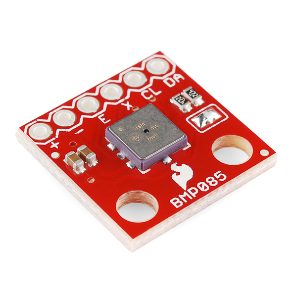
This is a breakout board for the Bosch BMP085 high-precision, low-power digital barometer. The BMP085 offers a measuring range of 300 to 1100 hPa with an accuracy down to 0.2 hPa in ultra-high resolution mode. It's based on piezo-resistive technology for high accuracy, ruggedness and long term stability. These come factory-calibrated, with the calibration coefficients already stored in ROM. Writing your own code for it requires some math, but there are plenty of examples and libraries available (see below).
This breadboard-friendly board breaks out every pin to a 6-pin 0.1" pitch header. VCC can be from 1.8V to 3.6V; we typically run it on a clean, regulated 3.3V supply. The analog and digital supplies (VDDD and VDDA) are tied to a single header pin, but are separately decoupled. It connects to a microcontroller via I²C bus (also known as TWI, or on the Arduino, the "Wire" library).
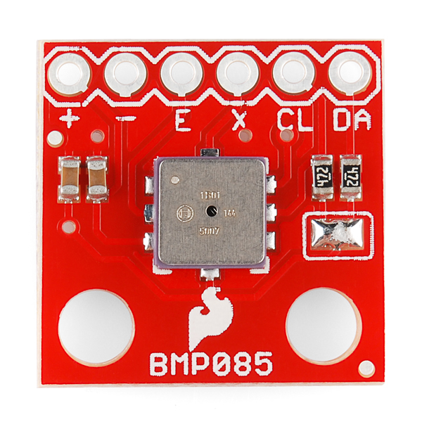
We've made some minor hardware changes this time around to address some suggestions from the comment section including the addition of a solder jumper to disable the I2C pull-ups.
Replaces:SEN-09694
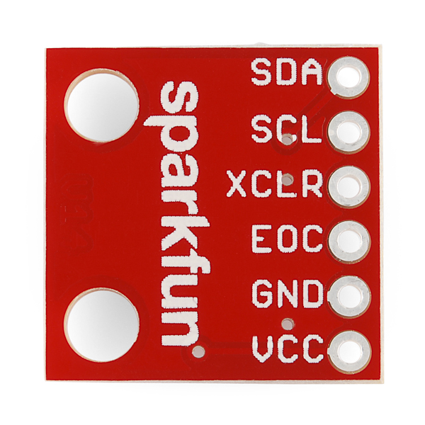
- Digital two wire (I²C, TWI, "Wire") interface
- Wide barometric pressure range
- Flexible supply voltage range (1.8V to 3.6V)
- Ultra-low power consumption
- Low noise measurements
- Factory-calibrated
- Includes temperature sensor
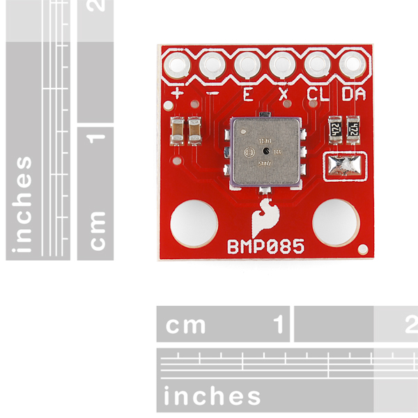
- Low-profile with a small footprint* 0.6" x 0.6" (15.24 x 15.24 mm)
Barometric Pressure Sensor - BMP085 Breakout Product Help and Resources
Core Skill: Soldering
This skill defines how difficult the soldering is on a particular product. It might be a couple simple solder joints, or require special reflow tools.
Skill Level: Noob - Some basic soldering is required, but it is limited to a just a few pins, basic through-hole soldering, and couple (if any) polarized components. A basic soldering iron is all you should need.
See all skill levels
Core Skill: Programming
If a board needs code or communicates somehow, you're going to need to know how to program or interface with it. The programming skill is all about communication and code.
Skill Level: Competent - The toolchain for programming is a bit more complex and will examples may not be explicitly provided for you. You will be required to have a fundamental knowledge of programming and be required to provide your own code. You may need to modify existing libraries or code to work with your specific hardware. Sensor and hardware interfaces will be SPI or I2C.
See all skill levels
Core Skill: Electrical Prototyping
If it requires power, you need to know how much, what all the pins do, and how to hook it up. You may need to reference datasheets, schematics, and know the ins and outs of electronics.
Skill Level: Noob - You don't need to reference a datasheet, but you will need to know basic power requirements.
See all skill levels
Comments
Looking for answers to technical questions?
We welcome your comments and suggestions below. However, if you are looking for solutions to technical questions please see our Technical Assistance page.
Customer Reviews
No reviews yet.
The BMP085 has been discontinued. Is there a drop in replacement?
Not currently. There are two recommended replacement ICs: the BMP180 and BMP280. We are looking at the BMP180 currently, but no word yet on when the 280 will actually be available.
Just a heads up, the weather reports value of approximately 29.92in or 101.325Kpa always references sea level. See the wikipedia entry below for more information. At first I thought I got a bad sensor.
http://en.wikipedia.org/wiki/Atmospheric_pressure
What changes are made to this design other than the new labelling? It looks almost the same as the old one.
Improved grounding, separately decoupled analog and digital supply, pullup enable solder jumper, and (sure to make some people very happy) MOUNTING HOLES.
For the next revision, or any other breakout board with this orientation, can you please swap the power pins?
if you do that, it will have the same pinout as the HIH-6130 bob...which has the perfect pinout to prototype with 28pin PICs like the 16F886, using port B.
Thanks, I should have checked schematic :)
RE: "accuracy down to 0.03 hPa", from the data sheet I believe the noise is 0.03 hPa, not the accuracy. The typical absolute accuracy is given as +/- 1 hPa, or roughly 8 M altitude, the relative accuracy is +/- 0.2 hPa, or about 1.6 M altitude
This agrees with what I've seen in the lab; the noise in the readings is on the order of 1 meter but if you can deal with lower data rates (< 1Hz) it filters down quite nicely.
The BMP085 can be used as a manometer gauge?
Why doesn't this breakout have a logic level shifter on board? The other BMP085 breakouts you can buy elsewhere are usually 3v and 5v compliant on the i2c. Worthless to use on Raspberry PI without separate logic level shifter. Cheaper to buy elsewhere because they include the shifter for the same cost.
Uh, the Raspberry Pi is a 3.3v machine so you don't need the level shifter to work with it. Got another rant in your pocket or are you ready to take yes for an answer?
Be careful with running this without a logic level shifter if using a 5v arduino. The quickstart guide shows it setup and connected without a shifter. It works fine without one for a while... mine worked for about 7 days before showing strange data and dieing. Time to buy a new one and a LLS.
On a Due (32 bit ARM) the signed and unsigned 16bit is a short. It appears to be a int under the AVR. I had to change the types for the constants read in from unsigned int/int to unsigned short/short. Otherwise the constants that should be negative won't be negative. Also, Wire.send() and Wire.receive() needs to be changed to Wire.write() and Wire.read() respectively. Lib change I'm guessing. This is on the demo code provided for the BMP085.
anyone without the arduino board coded the sensor in C language? please help!!!!!!!!!!!!!! desperate need of it
The Arduino code is C, in plain text, so I highly recommend at least looking at it.
I'm actually thinking about using this product for measuring air pressure in jars incubating soil for school experiment, because it seems to be an inexpensive option for pressure sensors. Does anyone know if the sensor can handle pressures above the maximum value (1100hPa)? The jars are expected to go a bit above the 1 atm. Will it return no values above 1100hPa or will it return some values that are not as reliable in the lower ranges? I'd buy one and try it out but thought I'd ask here first. Thanks for your help.
I want to use this sensor to sense air pressure and activate a small motor to equalize pressure of a small bottle. Any suitable microcontroller with I2C I can use with it ? Please advise.
Just gotta love the easy to spot read SparkFun boards, spotted this one in Secrets of Everything S01E03 (or, rather. it's predecessor, the SEN-09694) https://dl.dropboxusercontent.com/u/4306267/Secrets_of_Everything_S01E03_BMP085.png
Back on topic: Great little sensor, easy to get started with :)
If anyone is interested, I turned the bildr example into a library. It's still a little rough, but I've tested it on a pro mini and it seems to work.
https://github.com/TheBritKnight/BMP085Lib
Hi,
When I start the example sketch (where I just add an output of the raw values) I receive this : (I'm using it with an Arduino Uno)
Raw Temperature : 65535 Raw Pressure : 0 Temperature: 1918 *0.1 deg C Pressure: 314124 Pa Altitude: -10650.13 m
There is obviously a problem but I can't figure out where...
Does anybody have an idea ?
At this point I've tried at least 4 different Arduino sketches for this sensor and keep getting the same data which is obviously wrong: Temperature: -57.70 C Pressure: 179446 Pa Standard Atmosphere: 1.7710 Altitude: -5092.54 M
At least for the most part the temperature is consistent among the different sketches. However I'm testing this in my house which is obviously not that cold. I'm using an Arduino Micro (ATmega32u4). I've wired everything up correctly according to the schematics. Is there some additional calibration that I need to do with this board? One more thing I tried was to see if I could alter the temperature readings by placing ice near the sensor. Well, that didn't seem to change anything. I still get -57.70 C. I'm currently using this sketch http://ilabbali.com/code/Arduino_BMP085.cpp.
Turns out it was a logic level problem :-( I somehow missed that the board only accepts 3v logic. I hooked up 3v power, but I did not think about the I2C bus at all. Silly me.
So I just got another BMP085 sensor. Now I get a slightly different reading, but stil WAY off: Temperature: -94.50deg C Pressure: 164913 Pa Standard Atmosphere: 1.6276 Altitude: -4304.71 M
This seems to me that there MUST be some sort of calibration issue. Has anyone else seen this?
Recording barometer: I combined this sensor with a ProMicro 3.3V Arduino and a PCD8544 LCD display to keep a history of atmospheric pressure for the previous 84 hours. Go to the following instagram link to see it: http://distilleryimage7.instagram.com/3c317112778b11e28d6622000a1fbc43_6.jpg
Just a note for those using the BMP085 that I haven't seen anyone mention: light actually affects the readings (as it says in the datasheet). I have also confirmed this. For the most accurate readings, make sure the hole in the middle of the sensor is not exposed directly to bright light.
Can these be used to determine vertical motion? I don't need the actual altitude to be very accurate for my application, within a few meters is fine, can it detect small motions with an precision? In other words, will it detect accurately a vertical motion of only a few inches?
I don't think it would detect a few inches reliably. When used to maximum accuracy it's not all that fast, either.
Hi everybody. I'm getting negative value on altitude. What should I do? I used the example code posted here. PS:. I'm not underwater :P and I inversed for a couple of seconds the polarity from VCC to GND and from GND to VCC. Could it cause damage?
anybody?
There's either a code problem, or your device is damaged. If you contact customer service, you may be able to send it back for testing.
Is it possible to assign a new i2c address to this device? I would like to have six of these connected to the same arduino.
Unfortunately, you can't change the I2C address on these. However, you can use their XCLR inputs to keep all of the devices quiet except the one you're talking to.
Oups! I should have rtfm. Next silly question: When switching between different sensors, do I need to reread the calibration values for that particular sensor?
To be clear, each sensor will have different calibration coefficients, which will need to be used to get an accurate reading out of that particular sensor.
These values are set in stone for each sensor. Since they don't change, you could read them once and remember them, meaning that no, you don't need to re-read them. But you will have to use the correct set of values for each sensor.
I can think of a few ways to do this; you could re-read the values every time you access a different sensor, or read them once for all the sensors when you start up and store that data in a 2D array. However you do it, it might require a bit of hacking on the library code, which is expecting you to use the same sensor all the time. But it shouldn't be too hard to implement. Good luck!
I have bought this breakout one year ago, and had time to test it only today... I have used the example code and everything is fine, except reading the temperature register, which read back 0xffff ! While the pressure and calibration values read back fine.
Thus I have found a forum where people had same problem and found it was a problem in a batch of chips. Only change of the chip solved the problem. I want buy another breakout, but the chips in this new design are verified ?
I see there is a temperature rating of -40 to 85 °C on the BMP085, do you have a temperature rating available for the other components used in the breakout board?
We don't have an exact range for those parts, but as they are very rugged ceramic capacitors and resistors, the BMP085 is almost certainly going to be the limiting factor.
Thanks, it gets cold in WI!
Please send some of that our way, we could use it! =)
Hello, do you know what kind of algorithm is used in the oversampling modes (OSS = 1, 2, 3)? I'm thinking may be it would be a good idea to use the raw data (OSS = 0) and make my own filter, double exponential smoothing or similar.
Thanks
I'm not sure a filter makes much sense or difference here. Not a lot of point finessing out the fine details of the signal when the data you want is SUPPOSED to be a flat line. It's a barometer, not a microphone.
Considering it's a little chip, not a computer, I doubt it's anything fancier than sum(n)/n.
I've verified to my satisfaction that the part is as accurate as they claim, anyway. Took thousands of samples and did statistics, and the numbers I got fit the specifications to the nose.
I am looking at this sensor as a breath sensor, i.e. to detect someone blowing gently into an open pipe. Will this be fast enough to detect quick variations in the pressure generated by the blowing? After all, barometric (weather) pressure does not change that quickly....
The manual says up to 128 samples/second
The higher the sampling rate, the lower the accuracy, but I expect it'd read gross changes like that pretty well.
Is this 5V tolerant I/O pins? So can I connect to a Arduino 5V and supply 3v3 on VCC Sensor pin?
The I/O pins are not 5V tolerant, but the way I2C ("Wire") works is that the part can only actively pull a line to ground, otherwise the line "floats" to whatever the pullup resistors are connected to (3.3V). So if you're careful to only power this part with 3.3V from the Arduino, and only connect the I/O to the Arduino using the Wire library, you can successfully use this part with a 5V Arduino.
You are correct. But if your s/w lib activates pullups on the 5v mcu then you are stuffed. ie the internal AVR mcu 5v pullups of 50k plus the 4k7 on this board still give just over 3v3 and is probably ok. But if you add other breakout boards say at 5v with on board pullups then the SDA/SCL lines will creep towards 5v with the more you add. Until BMP085 goes bang. Worse - use a 5v mcu with a s/w lib that activates the internal mcu pullups and then remove the 3v3 supply to this sensor then SDA/SCL will pull up to 5v and it all goes bang. Happend to me! Connecting a 3v3 sensor like this to 5v mcu may work (depending on other i2c breakout boards you are using, what Vcc they use and whether they have onboard pullups). The wrong combination will kill ANY 3v3 sensors. Moral is - keep 3v3 sensors and 5v sensors on completely separate I2C buses. For the bus that matches your mcu Vcc then you can use its internal pullups - otherwise do NOT use the mcu pullups and insist the pullups are either added to one, or more, sensor boards or by you to the bus. ONE I2C BUS DOES NOT LIKE A MIXTURE OF DEVICES THAT EXPECT DIFFERENT VOLTAGES !!
Completely right. Ideally, each I2C bus should have one and only one set of pullups, and those to the correct voltage. There's valid controversy about the Wire library turning on the internal weak pullups by default, which it probably shouldn't do. But if you have proper external pullups to 3.3V, the addition of the internal WPUs (which are 20-40K) to 5V only adds up to 3.6V or so, which is high but acceptable. Thanks for the needed warning!
Has anyone attached a small hose for remote reading? If so, how did you do it?
I haven't done it with this sensor, but have for similar: just find a small enclosure to hold it (small box at mouser: 563-PB-1577 and lid: 563-PBC-1575-C ). Drill a small hole in the enclosure to attach a 1/8" brass fitting, which is the standard tube size I use in the wind tunnel (part 10BK1 at www.poweraire.com). The fitting doesn't need to butt up against the pressure sensor's hole -- in fact it's best to put it off to the side out of the way to minimize air flow that could occur directly over the hole. Cut a piece of breathable foam to both hold the sensor snugly and to prevent air from flowing too much over the sensor's hole. Drill another small hole to run the wires or find a panel-mount 6-conductor connector to mount to the box. When it's all rigged up, use hot glue to seal everything -- you only want air going in and out of the nipple (which is connected to your tube to wherever). Test it by blowing into the nipple -- you shouldn't be able to blow ANY air into it. If you want to be 100% on the integrity of the air-seals, attach a 10" tube to the nipple and drop the enclosure into some water. Shake all the bubbles off and then blow into the tube and look to see if bubbles form at your seals. Hope this helps
Epic failure. We epoxied a fitting to the top of the sensor. This worked great for about 10 minutes. When the fixture got repositioned on the bench, the pressure on the fitting warped the top ever so slightly. Turns out the sensor is extremely sensitive to the slightest structural deformation. So either go with iklln6's suggestion of small enclosure or epoxy a fitting to the board area around the sensor as opposed to the sensor itself.
iklln6 ...
Thank you very much for the detailed advice. I'll plan to build something similar.
Also, it looks like the Wire library has been updated since the code sample was posted. Once I make the fixes, I will upload the update. Does not look like major changes are required.
PS - The reason I ask is that the images show a mounted sensor, but just want to be sure that this is all that's needed.
Sorry for the noob question, but does "breakout board" mean it's just the circuit board or does this come with the actual sensor mounted and ready for deployment?
Need to know asap, filling out Purchase Request. Thanks in advance for the learning-curve help.
This board comes with the sensor already mounted. For future reference, any breakout-board that has the chip already soldered all the pictures will have it just like that when ordered. Also, any breakout boards that come un-populated are labeled very specifically as such and usually only have one picture showing what it looks after you finish soldering it yourself.
Has anyone used this for remote reading? I was thinking of attaching a small rubber hose to the chip.
It would be great a Proteus ISIS library of this component, that exist?
I tried to write 0x2E to the control register (address 0xF4 as in datasheet) which will configure the sensor to start measuring the temperature. When I wrote to the sensor, I was able get ACK when I sent out the device address with write bit. However, I got a NACK when I sent out the register address (0xF4) to slave. Is there anyone else who has the same issue?!