- Home
- Product Categories
- Arduino Shields
- 4x4 Driver Shield

4x4 Driver Shield
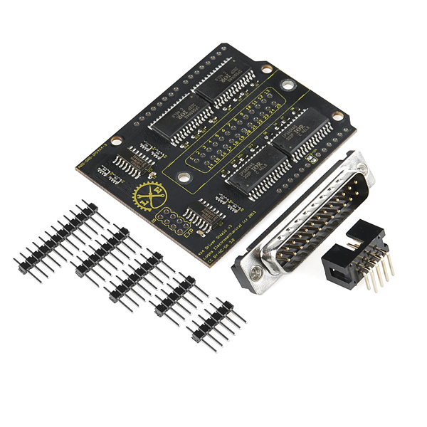
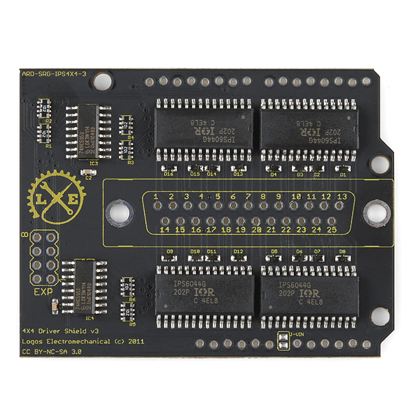
The 4x4 Driver Shield is designed to enable users to switch DC loads up to 5A at up to 30V with no heat-sinking. It is ideal for such applications as driving solenoids, relays, and small DC motors. It uses International Rectifier IPS6044 quad channel fully-protected high side MOSFET switches, which include over-temp, over-current, and under-voltage protection. The high-side topology is safer in many applications than the more common low-side topology because a short to ground cannot energize the circuit while the switch is turned off, as it can with a low-side switch. This shield can also be used to drive four unipolar stepper motors.
The board is built with generous traces to handle the current with minimal voltage loss and heating on the board. A pair of 74AHCT595 8-bit shift registers allow the control of sixteen high current channels from only four Arduino pins using the shiftOut() function, and make it possible to daisy-chain as many as 25 boards off a single host, for a total of 400 high current channels.
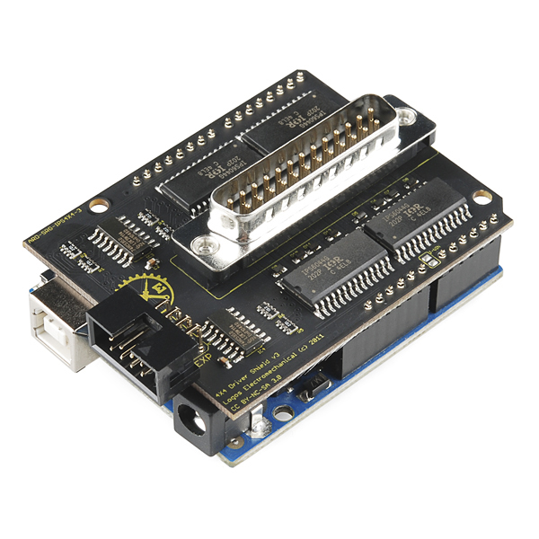
- Arduino shield form factor compatible with all shield compatible Arduino variants and clones.
- Sixteen five amp high side driver channels
- Shift register control allows daisy chaining of up to twenty-five boards for a total of four hundred channels
- Uses only digital pins 7, 8, 11, and 13, leaving all serial, PWM, and analog input lines free.
- Mapped to the hardware SPI bus on the Arduino Uno, allowing high speed data transfer.
- Inexpensive and robust DB-25 male connector carries power and outputs
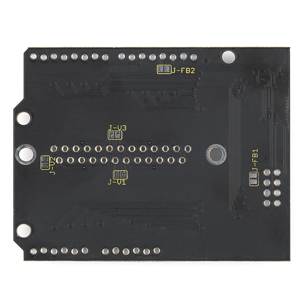
- Four separate power supply circuits allow maximum application flexibility.
- Ships with loose connectors for end user flexibility, including use with non-Arduino hosts.
4x4 Driver Shield Product Help and Resources
Core Skill: Soldering
This skill defines how difficult the soldering is on a particular product. It might be a couple simple solder joints, or require special reflow tools.
Skill Level: Rookie - The number of pins increases, and you will have to determine polarity of components and some of the components might be a bit trickier or close together. You might need solder wick or flux.
See all skill levels
Core Skill: Programming
If a board needs code or communicates somehow, you're going to need to know how to program or interface with it. The programming skill is all about communication and code.
Skill Level: Competent - The toolchain for programming is a bit more complex and will examples may not be explicitly provided for you. You will be required to have a fundamental knowledge of programming and be required to provide your own code. You may need to modify existing libraries or code to work with your specific hardware. Sensor and hardware interfaces will be SPI or I2C.
See all skill levels
Core Skill: Electrical Prototyping
If it requires power, you need to know how much, what all the pins do, and how to hook it up. You may need to reference datasheets, schematics, and know the ins and outs of electronics.
Skill Level: Competent - You will be required to reference a datasheet or schematic to know how to use a component. Your knowledge of a datasheet will only require basic features like power requirements, pinouts, or communications type. Also, you may need a power supply that?s greater than 12V or more than 1A worth of current.
See all skill levels
Comments
Looking for answers to technical questions?
We welcome your comments and suggestions below. However, if you are looking for solutions to technical questions please see our Technical Assistance page.
Customer Reviews
No reviews yet.
Questions: --> How quickly can the shift registers operate? I need approximately 10,000Hz sequencing operation for a special application. Basically, I need one output to power-off while the next output immediately power-on, at approximately 100 microsecond interval, in a high speed sequence, over up to 64 outputs. This is for a very special application.
The shift registers are 74LS595s, according to the schematic. The datasheet for these shift registers says they are capable of handling a 20 MHz clock (http://datasheet.octopart.com/SN74LS595D-Texas-Instruments-datasheet-151133.pdf).
The limiting factor is likely to be the Arduino. The shield is designed to use the hardware SPI bus, which can run up to 8 MHz. For 64 outputs, you should be able to push a new sequence out in ~8 microseconds.
However, if you just want to light up a single output in sequence over the 64. That's even faster. You push all zeros, then you push a single one. You can push that one down the stack by setting the data line low then strobing the clock and the latch lines (in that order). The new zero will push your one down the line when you strobe the clock and strobing the latch will push the new value to the outputs. You can see how this works by playing with the interactive 595 simulator at http://conductiveresistance.com/interactive-595-shift-register-simulator/
Nice looking board, it seems feasible to use this as a grblshield.
Dont think so, it is not very usefull for controlling stepper motors and if I see this correctly it can control DC motors only in 1 direction - see documentation.
This may sound foolish but the description says it can drive 4 unipolar stepper motors, does that mean that it could drive bipolar steppers? Would it be particularly hard to do?
Does anyone have any code for using it to PWM LEDs?
Thermal vias were not used to connect to ground planes, making soldering a bit difficult.
It would be rather useless if thermal vias were used... The whole idea is to achieve performance as close to a solid copper sheet as possible to conduct as much heat as possible from the switches... Thermal vias would defeat that intent.
Actually, this is more than just a bit difficult. All the solder connections are easy to get right. Except for the connections made to planes. It's next to impossible to not have cold solder joints due to the lack of thermal vias. This is pretty important, especially for a $55 module.
looks like this uses 5V input from the arduino....is there a 3.3V version for the Due??
The shift registers work correctly with 3.3V inputs, so the same type works with both.
This might seem extremely basic, but what kind of connector is the 8 pin one that's included with the board? Can't seem to locate the female connector that goes into it.
It fits a standard 8-pin IDC ribbon connector.
hey, i was wondering if anyone has used this shield to control 8 DC motors ( 4.2A, 12-18V) or even 1 DC motor. If anyone has, could they possibly help me. Thanks.
Has anyone used the Arduino Library link above to drive the shield? I have not had any luck yet. The example code is missing a few crucial details that I am unable to sort out.
Your link to the Eagle files isn't Eagle files, there Gerber files...
hello, can this driver be used with the GRBL 0.8a software ? working on making an CNC platform.....
Hi,
I'm new to arduino/electronics I'm wondering if anyone thinks this might be suitable for use with some 12V LED strips? I have around 7 sections of single-color 12V LED strip (non-addressable), most of which will be around 0.5A. I just want them to switch on and off in sequence at max of maybe 5Hz. I wasn't planning to do any PWM but looks like this wouldn't be possible using these pins and the shiftOut() method anyway?
It's for a wearable project so liked the idea of this small self contained shield that doesn't require me to build a PCB with mosfets.
Any thoughts appreciated.
"switch DC loads up to 5A at up to 30V" Ipso facto, yes it can, but its hella pricy, might be overkill. Snag two 12v MOSFETS and a perfboard and Bob's your uncle for under $20, and probably under $10 if you aren't paying shipping.
new board seems to have different pin from arduino. Can some one give me the right define condition I try with with: #define DATPIN 13
#define SCLPIN 12 #define LATPIN 7 #define MRPIN 8
#define INDPIN 2
but doesn't work.
I search a little exemple to test all output, thanks in advance
According to the schematic, DATPIN is now pin 11 and SCLPIN is now pin 13, in order to enable the user to write to it using the SPI hardware.
PS -- where did you find that code snippet?
Do you carry the right size ribbon connectors for the 4 x 2 connector on this board ?
The schematic link doesn't open the pdf file.
It can be funny to see a couple of these shield stacked and not be able to connect a DB25 except for the topmost one :) May be in a future revision, a right angle DB25 connector at the end side of the board can help. Or are you aware of a very very low profile DB25 connector ?
That's a great suggestion for a future revision, and would make stacking multiple boards much easier. In the meantime, you might consider using DB25 IDC (Insulation Displacement Connectors) that crimp onto a ribbon cable; you could then fold the ribbon cable out the front or back of the stack, though you might still need an extra set of headers to add some airspace between this and the next shield. And you can always solder wires directly to DB25 footprint.
Soldering wires directly to the shield is probably safest, if you're running any kind of current. When you're playing at 5A, 28AWG ribbon cable is known as a "fusible link". ;)
Even the D-sub's per-pin max current of 5A strikes me as a bit optimistic. If I was running that continuously, I'd be making really sure my connector was name-brand and had some airflow to keep cool. No cheapies!
Any chance of a breakout for the IPS6044/CDBU0240? With the DGx pins also routed to the header?
not sure, but you can check the schematic above.