- Home
- Product Categories
- Development Tools
- Electric Imp Shield

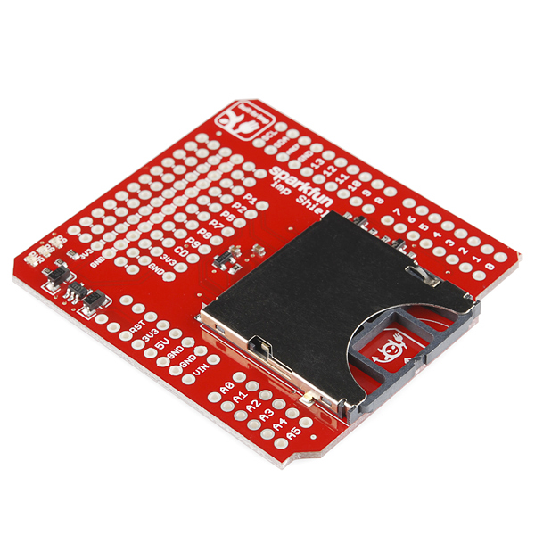
Electric Imp Shield
If you aren't familiar with the Electric Imp, it essentially provides an easy, integrated way to connect almost any hardware device both to other devices and to internet services. It's more than just a WiFi card, or even a WiFi module with processing built in - it's an integrated platform that deals with the drudgery of connectivity, allowing you to concentrate on the application instead of the mechanics. Of course, if you're developing for it you'll need a way to get in there and poke around. The Electric Imp Shield allows you to connect your Arduino project to the internet through your home WiFi network. This way, your Arduino can take advantage of the Imp Cloud service and connect to HTTP APIs.
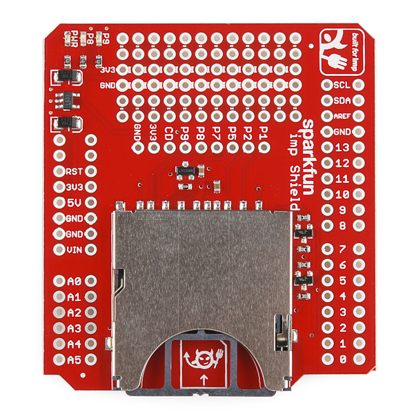
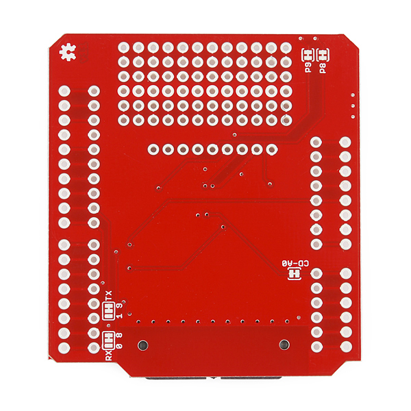
The Shield connects one of the imp's UARTs (Imp pins 5 and 7) to either the Arduino hardware UART or a software serial on pins 8 and 9. It defaults to the software serial, but there are jumpers on the bottom side to set it to the hardware serial. A couple imp pins (8 & 9) are also connected to LEDs. They can be disconnected via jumpers on the bottom, if you'd like.
Because the Electric Imp can draw up to 400mA on the 3.3V line, this shield has its own voltage regulator which is fed from the 5V Arduino line. Most Arduino compatible boards should be able to handle this amount of draw but beware that some clones that use less robust VREGs could see trouble.
Electric Imp Shield Product Help and Resources
Wireless Arduino Programming with Electric Imp
February 24, 2014
Reprogram your Arduino from anywhere in the world using the Tomatoless Boots wireless bootloader with the Electric Imp.
Electric Imp Breakout Hookup Guide
June 25, 2015
An electric imp HUG! Provides an overview of the imp card and breakout. Both hardware and firmware subjects are covered.
Arduino Wireless Communication via the Electric Imp
April 8, 2014
How to communicate between an Electric Imp and Arduino using serial.
Core Skill: Soldering
This skill defines how difficult the soldering is on a particular product. It might be a couple simple solder joints, or require special reflow tools.
Skill Level: Rookie - The number of pins increases, and you will have to determine polarity of components and some of the components might be a bit trickier or close together. You might need solder wick or flux.
See all skill levels
Core Skill: Electrical Prototyping
If it requires power, you need to know how much, what all the pins do, and how to hook it up. You may need to reference datasheets, schematics, and know the ins and outs of electronics.
Skill Level: Rookie - You may be required to know a bit more about the component, such as orientation, or how to hook it up, in addition to power requirements. You will need to understand polarized components.
See all skill levels
Comments
Looking for answers to technical questions?
We welcome your comments and suggestions below. However, if you are looking for solutions to technical questions please see our Technical Assistance page.
Customer Reviews
No reviews yet.
I just got this shield and it is working. I also have this display https://www.sparkfun.com/products/11442. But when I use the Wire library functions my sketch stops working right after Wire.endTransmission();
I am using the Arduino I2C pins A4,A5 on the shield.
Dumbass, I forgot Wire.begin()
I like this board and the Imp. I got it up and running in just a handful of hours. I had to cut the "CS" trace because that pin was already used by my system. I also cut the traces that were defaulted for software serial and solder-jumpered the UART 57 (pins 5 and 7) of the Electric Imp to the Arduino. I am using Leonardo boards so the hardware UART was available.
I started with the code by Jim Lindblom and modified it slightly to work on my system.
Now my Arduino-based testing machine is on the web. Awesome!
Does any one know if this shield has the ID chip for the imp In the website it says we will need an ID chip for the imp.Does this have one??
Look at the schematics of the board, the necessary crypto chip ATSHA204-TSU is onboard
My imp keeps resetting, and I suspect that it's because it's not getting enough power from the 5V arduino pin. Is there a way to feed it from Vin instead?
Would this work with the Raspberry Pi?
My Imp shield seems to have some bad connectors on the imp socket. I have to press lightly on the top of the metal card housing to get all the connectors to make contact with the rest of the circuit. Any tips? Do you have an improved shield?
If you have a hot air gun, you can try reflowing the socket and see if you can get a better connection that way. We are looking into this currently as far as improving the reflow on our end, but currently this is the only shield for the Imp.
Do the I2C lines (from imp pins 1 & 2) require pull-up resistors for this shield?
I've got some sample code (and design for my own imp + arduino on one board) here. they're for sale, if you're interested.
Hi guys, I'm trying to read voltage using ADC on electric imp. When using the pin 1 and 2 I get correct values. If i'm using pin 5, 7, 8 or 9 I get a voltage near 2.9 or so... I got this board and only soldered a stackable header on the pins 1 to 9 and 3.3 V an GND.
Do you have any clue on what it can be?
I found why.. I just checked the datasheet! duhh
I purchased stackable headers for my arduino and imp shield, but was disappointed to find that the imp doesn't sit flush on the arduino due to the USB port sticking up too high. Also, when I put my stackable headers through the imp and into the arduino, I found that the connection is very unstable -- meaning that I have to apply pressure on the headers to get it to make a solid connection and actually power the imp. Anyone else have this problem? I'm fairly new to using shields, am I doing something wrong?
so you cant power this board independently of an arduino?! Seems strange - was hoping to use this board as both a arduino shield and sperate imp board. Would be interested to know the reason behind this decision?
EDIT: well dont I feel like a n00b - so it can be powered from the 5V and GND pins not the Vin and GND pins which are separately supplying the arduino. Sorry guys!
.
Might want to mention above that the A0 line is connected to CD (Card Detect?). Had me going for a while, luckily my accelerometer seems to have survived the experience.
Sparkfun, what about making another shield with the sd card on the bottom?
The idea of a "crypto chip" on OSHW concerns me. Does it have keys or similar loaded into it, or can anyone buy the atmel part and make it work?
So, the main thing the ATSHA chip is used for is its unique ID. This allows us to bind software to an ID for every device in the field.
For commercial devices, a 256 bit random number is locked into a page on the ATSHA and shared with the server when the device is tested at the device maker's factory. This means at any time after that, the server can verify that the device claiming to be, say, an Acme Washing Machine, is actually this device by issuing a MAC challenge to the ATSHA via the imp card.
If someone cloned the Acme Washing Machine, they wouldn't have this random number and hence couldn't answer the MAC challenges (and wouldn't get Acme's firmware).
If you're not a manufacturer, then this functionality isn't used... just the unique ID.
This is a neat little chip that anyone can use, check out the datasheet yourself.
Cryptography is actually one of the most important applications of open source. Far too often, proprietary cryptography systems use "security by obscurity", and as soon as someone finds a (the) weakness, the system breaks wide open. But if you give out all the details of your system, giving lots of people a chance to break it, it will be (and is in practice) vastly more secure. In open cryptography systems, it is key management that provides the security, which is part of what this chip can do.
Any possibility to have the Sparkfun Eagle Libraries updated with the Imp components?
I've totally been slacking on updating the library.
Just posted them to the github repository. Electric Imp footprint is in SparkFun-RF.lbr and the ATSHA204 is in the SparkFun-DigitalIC.lbr.
Thanks Jimb0! As always sparkfun rocks!!!!
Anyone can. It is just an ID chip so the imp can ask the cloud server what firmware to download for that particular device.
A bit steep in price. I made a shield for Arduino using the BatchPCB service. About $12.50 for the board. With shipping and processing fees, it came to about $23. With shipping this package, it'd be about $24 for First Class or almost $28 with Priority Mail. Plus another $1.50 for header pins. The "Duino" listed on Imp's website is $20 but they included headers, MCU, etc. I was holding off buying an Imp until the shields and breakouts came out, but due to the high cost of these, I think I'll wait a bit longer or build my own. It's still a cool idea that I want to experiment with though.
Yeah, and it doesn't exist yet :-)
Technically 500 of them exist, but until we've done the software for them we'll just sit on them :)
True!
I'm new to Arduino and shields... Do I have to solder my own headers to connect this to the Arduino or are they already on the board? (the picture would seem to indicate I need to solder them)
I just did it today. I am not terribly good at soldering and it took me a few minutes and came out nicely. It shouldn't be too tough.
yes, you will need to solder your own. check below, we have stackable header kits.
we don't include headers because some people might want the stackable ones, and others might just want straight headers, or some OTHER people might want something different.