- Home
- Product Categories
- Books
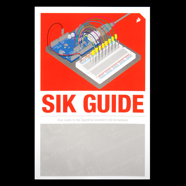
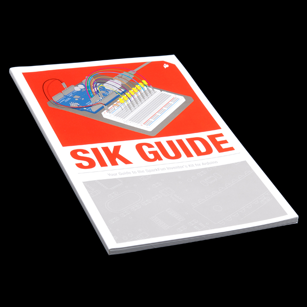
- SparkFun Inventor's Kit Guidebook

SparkFun Inventor's Kit Guidebook
Replacement:BOK-11976. This book has been updated for the new version of our SIK. Go check it out! This page is for reference only.
We've created a brand new edition of the full-color SIK manual! Updated graphics, code revisions and in-depth instruction have been added to make learning basic electronics even easier! Make your way through the example circuits and you'll learn all about:
- Blinking LEDs
- Controlling a toy motor
- Controlling a servo
- Making (bad) music
- Using buttons as inputs
- Twisting a volume knob
- Detecting ambient light
- Reading temperature
- Controlling big devices
- Mixing LED colors
More!
Buy extra kit guides for classroom or workshop situations when people need to share kits, or just keep a few as backups for when one of them is inevitably wiped out in a tragic coffee-spill accident.
SparkFun Inventor's Kit Guidebook Product Help and Resources
Core Skill: Robotics
This skill concerns mechanical and robotics knowledge. You may need to know how mechanical parts interact, how motors work, or how to use motor drivers and controllers.
Skill Level: Noob - You will be required to put together a robotics kit. Necessary parts are included and steps will be easy to follow. You also might encounter basic robotics components like bearings, mounts, or other hardware and need a general idea of how it goes together.
See all skill levels
Core Skill: Programming
If a board needs code or communicates somehow, you're going to need to know how to program or interface with it. The programming skill is all about communication and code.
Skill Level: Rookie - You will need a better fundamental understand of what code is, and how it works. You will be using beginner-level software and development tools like Arduino. You will be dealing directly with code, but numerous examples and libraries are available. Sensors or shields will communicate with serial or TTL.
See all skill levels
Core Skill: Electrical Prototyping
If it requires power, you need to know how much, what all the pins do, and how to hook it up. You may need to reference datasheets, schematics, and know the ins and outs of electronics.
Skill Level: Rookie - You may be required to know a bit more about the component, such as orientation, or how to hook it up, in addition to power requirements. You will need to understand polarized components.
See all skill levels
Comments
Looking for answers to technical questions?
We welcome your comments and suggestions below. However, if you are looking for solutions to technical questions please see our Technical Assistance page.
Customer Reviews
No reviews yet.
wow, they sell the book for really cheap, AND they give away the PDF version for free
The PDF version does not seem to have page numbers. Is it just me?
It's not just you :) The PDF version along with the current booklet version both do not have page numbers. We're getting this fixed soon!
-Casey
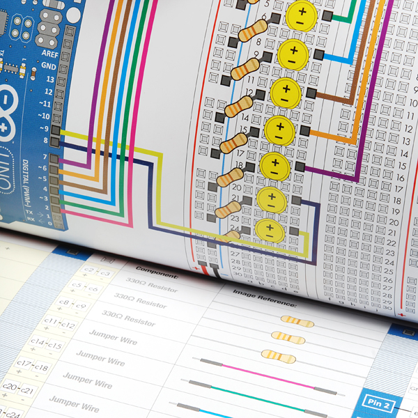
The guide has a bug in the motor circuit 12 on page 64. The original version had a 10k resistor, which brought the affects of this bug out even more. This version uses a 330 resistor, which appears to work, but still cuts the full use of PWM.
Pin 9 should run directly to the BASE of the transistor and then a 10k pull-down resistor should be used running from the same (PIN9/BASE to Ground). See: http://bildr.org/2012/03/rfp30n06le-arduino/
The way it is setup on page 64, a 330 resistor runs between Pin 9 and base.
PDF Version has an error in example 13's circuit diagram. The diode connecting e7 to f7 should be rotated 180 degrees such that the black tab is on f7 rather than e7. My print copy reflects this.
Hi, I also caught this flyback diode issue for the "Relay" diagram. Our university students ran into this issue for a few days before I figured it out. Like you said, if the diode is reversed the opposite direction then it works as it should. Just wanted to comment also so that people can find this easily if they run into issues with their guide version. Thanks for the initial post!
Thanks for the catch! It should be fixed on the new revision.
Hi ;
How do they draw Arduino 3D project image. it isn't fritzing. what kind of programmes? Please help me?
We use SketchUp for our 3D layouts for products, but our marketing department generates any 3D images in our guide. I believe they use Illustrator.
In my previous comment, in the paragraph describing the photo resistor issues, please substitute "photo resistor" for "temperature sensor".
Both the Photo Resistor (#6) and Temperature Sensor (#7) circuits have problems.
In the Photo Resistor circuit, the table that specifies which components to use and how to hook them up has temperature sensor on the wrong side of the voltage divider. So as ambient light brightnesses increases, the brightness of the LED decreases.
In the Temperature Sensor (#7), the +5 volt and GND pins of the TMP36 chip are reversed in the documentation. This led to the indicated ambient temperature as being about 20F below the actual ambient temperature. Reversing the TMP36 fixed the problem, for a while. After running for about 15 minutes, the indicated temperature started rising to large values (about 450F), the TMP36 smelled as if something burning (it was) and it was way too hot to touch). I'm assuming that running the TMP36 chip backwards damaged the chip.
Hi I am a noobie with Arduino.
Most of the examples in this book uses the Arduino Uno board. Can an Aurduino Due be used instead? Is all that I need to convert is the 3.3 to/from 5 V level logic using a logic level converter? I have noticed that some of the components are chosen so they worked with the 5V system that fit the Uno. It seems that I have to change some components to accomodate the 3.3V or will a logic level converter good enough to for me to follow examples on this book?
Thanks,