- Home
- Product Categories
- 7-Segment
- SparkFun OpenSegment Serial Display - 20mm (Red)

SparkFun OpenSegment Serial Display - 20mm (Red)
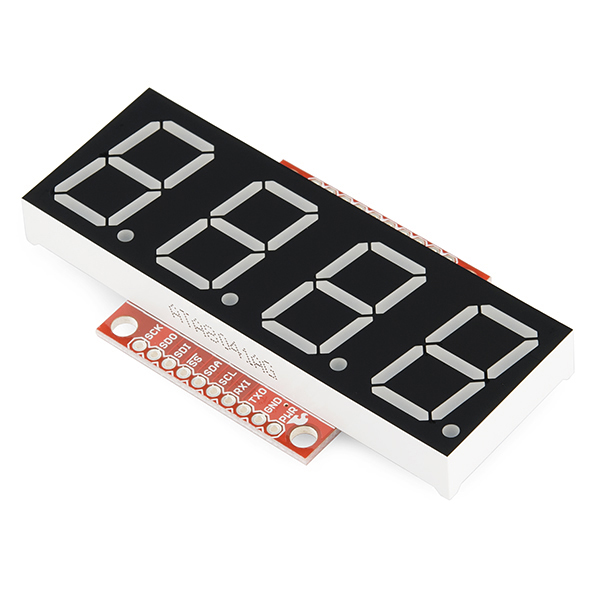
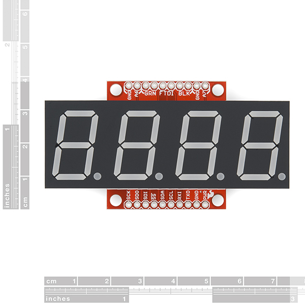
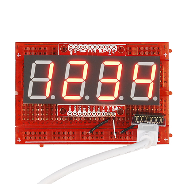
OpenSegment makes it easy to add a large 7-segment display to your project. Because larger 7-segment displays pull more power than a microcontroller is able to drive directly, the OpenSegment has 8 PNP and 4 NPN transistors in order to drive the segments at their maximum brightness!
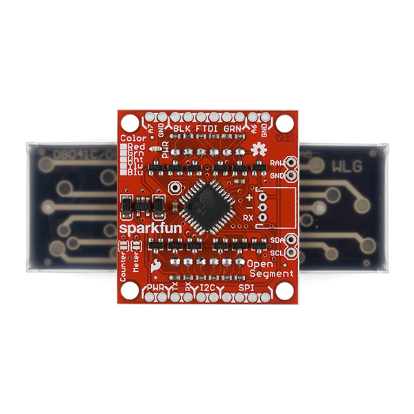
The on-board ATmega328 receives data over multiple digital interfaces (such as TWI, UART and SPI) and does all the PWM and upkeep of the display so your main controller doesn't have to. There are even two built-in functions that can be activated with solder jumpers. The counter function simply counts up or down, incrementing when you pull down SDO and decrementing when you pull down SDI. The meter function gives you a voltage read-out of the ADC!
OpenSegment runs at 5V and uses a standard FTDI connection for programming. The board is pre-flashed with a bootloader compatible with the Arduino Pro Mini @ 8MHz setting under the Arduino IDE. This firmware is an updated version of the Serial 7-Segment firmware designed to run on both devices. The commands will be largely the same except, of course, that this display only has decimals and no colon. See the datasheet for the Serial 7-Segment below to get an idea of the serial command set.
- On-board Transistors Allow Display to Run at Full Brightness
- Serial Commands Available to Adjust Brightness, Baud Rate, and I2C Address
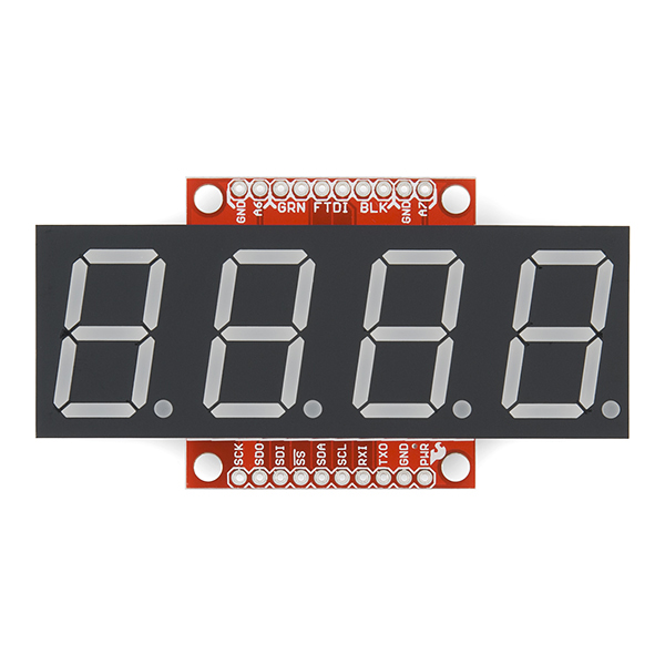
- Individual Control for Digits and Decimal Points
- Arduino Compatible with FTDI Header
- Built-in Meter and Counter functions
SparkFun OpenSegment Serial Display - 20mm (Red) Product Help and Resources
Core Skill: Soldering
This skill defines how difficult the soldering is on a particular product. It might be a couple simple solder joints, or require special reflow tools.
Skill Level: Noob - Some basic soldering is required, but it is limited to a just a few pins, basic through-hole soldering, and couple (if any) polarized components. A basic soldering iron is all you should need.
See all skill levels
Core Skill: Programming
If a board needs code or communicates somehow, you're going to need to know how to program or interface with it. The programming skill is all about communication and code.
Skill Level: Rookie - You will need a better fundamental understand of what code is, and how it works. You will be using beginner-level software and development tools like Arduino. You will be dealing directly with code, but numerous examples and libraries are available. Sensors or shields will communicate with serial or TTL.
See all skill levels
Core Skill: Electrical Prototyping
If it requires power, you need to know how much, what all the pins do, and how to hook it up. You may need to reference datasheets, schematics, and know the ins and outs of electronics.
Skill Level: Noob - You don't need to reference a datasheet, but you will need to know basic power requirements.
See all skill levels
Comments
Looking for answers to technical questions?
We welcome your comments and suggestions below. However, if you are looking for solutions to technical questions please see our Technical Assistance page.
Customer Reviews
4 out of 5
Based on 1 ratings:
Works great
This is working really well. I wish they had a 2 digit version
When I peeled off the protective plastic, some adhesive was left behind, spoiling the display's appearance. Is this a common problem? Is there some technique for removing the plastic so that all the adhesive goes with it?
Fooey! Sorry to hear that. The plastic should come off without problem or leave residue. Goo-gone may help but I suspect it will remove some of the black surrounding material as well. If it's really bad please contact customer support for a replacement.
I am wanting to use two of these on an I2C bus. Is there any simple method to change the address of the device so that I can?
There is a command to change the I2C address of OpenSegment. I just added an example to demonstrate how to do this. You can find all our examples here. The example to change the I2C address is here. Hope this helps!
So this will need an outside 5v source to run at full brightness? Will it still function if using a 5v pinout on an arduino uno r3?
Providing OpenSegment with 5V from the 5V pin on the Arduino works great and is just as bright as if you powered it from an external 5 to 7V source.
Got one of these wanting it to work with a Picaxe 08M2 and 3 days later, no luck. All I see is 1234 on the display. Nothing I do has any effect on the display. VERY disappointed! It was suggested I may have messed up the default baud rate of 9600 and was provided with the "fix" for this. At least the display acted as described when I did the procedure but did not fix my problem. Still am unable to get the display to respond to ANY code I send it :(
Sorry you ran into problems! If you think your OpenSegment might have gotten into a weird baud rate there is a way to reset to factory defaults (9600bps). The tutorial is here. I hope you find a way to get your Pixaxe to talk to OpenSegment.
Can this be used outdoors without the display fading due to the sun?
I have four of these displays. I plan on upgrading the software to measure the scale speed of a model train, using the "inc/dec" pins of the current board as start/stop inputs from a digital IR Detector. I plan on just adding another Mode to the current software, and a few extra Commands. I plan on making the software changes generic enough that it can measure any speed, at any scale (maybe with a few limitations), to 0.1 MPH or 0.1 KPH.
The major problem I would have is that the current board does not have a 8MHz crystal on it, so the timing would be to the Factory Default of 10 percent error. I have the crystals and capacitors on order, so I can tack them onto the back of the board, and change the Boot File, to get the accuracy I need.
Currently, the board is used for display, counting and voltage measurement. None of these require the higher clock accuracy. But are there any plans to replace the Mode Pads on the board with a crystal and capacitors to do higher accuracy timing also? I would definitely purchase a board that was modified that way. Alternatively, would it be possible on the next Board Revision that you could lay out the traces so there will be through-holes for a crystal and capacitors? That latter may be easier, since there are already through-holes for the traces to the Mode Pads that could be used for the crystal and capacitor holes.
Jerry
I have unsuccessfully searched for a closed housing to properly mount this display in a panel in an industrial environment. Does anybody know where I can get such a housing ?
Interesting question. Most of the sealed solutions I've seen have a cutout in the enclosure for display and a membrane switch with a clear window (I did some bad googling and found this example) and a strong adhesive backing. This very effectively seals the enclosure. I've also seen 'smoked' or tinted plastic used to seal apertures and increase the contrast of a 7-segment display (just like a classic digital alarm clock).
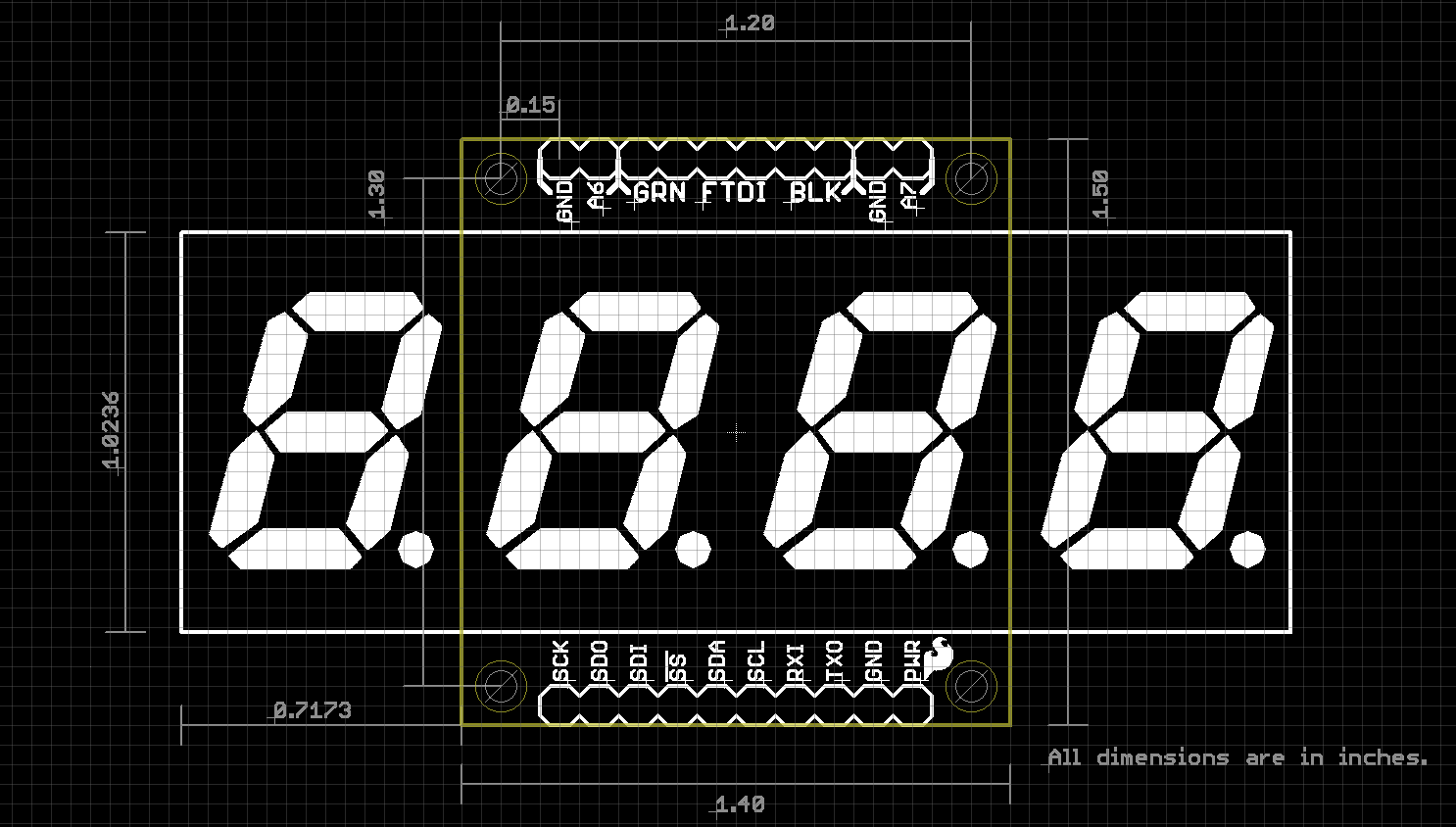
The Dimensional Drawing is at https://raw.github.com/sparkfun/OpenSegment/master/Hardware/OpenSegment-Dimensions-v13.png
Shoot! Thanks for pointing that out. Looks like we shuffled our repo around a bit. We'll update those links.
And code examples for a PicAxe, preferably smaller like 08M?
Unfortunately I'm not enough of a PicAxe expert to write them. If anyone else does (or if you do!) please let us know and we'll roll the examples into the github repo + docs and give lots of thanks to the authors!
Had the same issue with my red version that was mentioned on the white version. I tried the solder jumper to put it into count mode, but that didn't work (all I got was 1234). Used the Arduino code Nate pointed to and just changed modes that way. Works fine now (but I wish the jumper had worked). /K
Sorry you ran into troubles! We had an firmware bug with the first batch of displays that failed to check the solder jumpers. Looks like you fixed it yourself. Thank you. If you have any more issues please don't hesitate to say hello.
I have been completely unable to upload code to either of two copies of this unit.
When I use the FTDI basic breakout, the reset occurs, and avrdude initially seems to communicate successfully with the boot loader. But then it tries to send one byte, fails to receive any response, and gives up. This is the avrdude output.
I have also tried flashing the latest optiboot using an stk500 compatible ISP programmer (Pololu AVR Programmer), but that doesn't seem to work either. The programmer doesn't seem to be able to communicate with the 328p after reset.
In short, nothing I do seems to be able to change the behavior of the display's MCU. It still boots the original firmware.
Has anyone successfully programmed one of these units once assembled?
Also, should it be possible to program via ISP, considering how the AVR is connected?
OK, I was able to reprogram it (to unresponsiveness) using the ISP programmer, and then recover it by uploading the contents from my other OpenSegment copy.
I still can't get it to accept an arduino-style upload via serial though.
Got it accepting programs via the FTDI.
It appears to have similar to this issue, where a 500ms timeout in the bootloader is too short for the FTDI/avrdude combination.
I raised the timeout to 1S, and also changed the baud rate to 57600. I had to burn that bootloader using an avrisp, but now I can upload sketches.
Is there an available pin on this that could be used to count the high frequency pulses from this light sensor?
I'd like to make the brightness of the display self-adjusting. I've done this to some extent with the older 7 segment Sparkfun displays. Note that I disabled saving of the brightness level to avoid wearing out the EEPROM!
But I was reading and processing the light levels externally and using the display's command language to adjust the brightness. It worked, but it was slow and cumbersome. And the analog light sensors I've tried don't have much dynamic range for normal indoor light levels.
I'm hoping the pulse-emitting sensor could have more detail at low light levels. Is there a pin on the OpenSegment that could be used to count such high frequencies?
Really interesting question. Unfortunately there's almost no GPIOs left. You might be able to hook into the TX pin on the board (other than during bootloading, OpenSegment currently doesn't transmit anything out) and write an 'on-change' interrupt to capture the incoming pulses. You'd really only need to count the milliseconds between two pulses every few seconds and adjust the brightness of the display accordingly. You'd probably only need to check the pulse train coming from the TSL235R light sensor once a second. Changing the brightness more often than a second might look a bit odd.
I assume these are the same displays as your 1" 7-Segments that are actually 0.8" tall? And why did you use the 328P over the 32u4? I would have preferred if you used different firmwares instead of solder jumpers for the different modes, and breaking out more pins would have been awesome.
But really, those are just small things. Thank you for listening to our feedback and making these, they look great!
Good points. Here's my thoughts:
Yep, these are the same 1" displays that are actually 0.8" digits. We (and I think most others?) categorize a 7-segment display by its outside dimensions.
The ATmega32u4 is good if you want to remove the FTDI from an Arduino. Because this product is not meant to be a full blown Arduino (we don't expect anyone to reprogram the board) the built in USB functionality of the 32u4 is not needed (and is just extra cost). Having a product with a microUSB on it is interesting, but we try to design stuff for the 90% user and I think 90% of users just need a serial 7-segment display, not a field boot-loadable Arduino with a 7-segment display attached.
You can access the different modes using the solder jumpers or different serial commands. Offering different products with different firmwares is definitely a way we could go in the future. I assumed folks would want the flexibility but let me know if I'm wrong.
More pins: but... but... there's not any left! :) Check the schematic. I had the shoe-horn the solder jumpers onto the xtal pins.
Mouser (a significant other) categorizes LED digit displays by the actual digit height. The product titles in the datasheets for displays made by Luminex, Kingbright, Lite-On, Avago, etc. also go by the digit height, not the case size. Perhaps you are thinking of dot matrix LED type displays, which are categorized by their case size.
I stand completely corrected. You are right, the products are usually called out by digit height not overall height.
We've changed the product titles from 0.1" to 20mm. We've found a lot of displays on Mouser/Digikey are listed in metric so we made the switch. Let us know if anything else sticks out.
Yes I agree with rsp, should be actual digit height, that's always the way I've known in in the industry and that goes back a long way.