- Home
- Product Categories
- Development Tools
- RS232 Shield

RS232 Shield
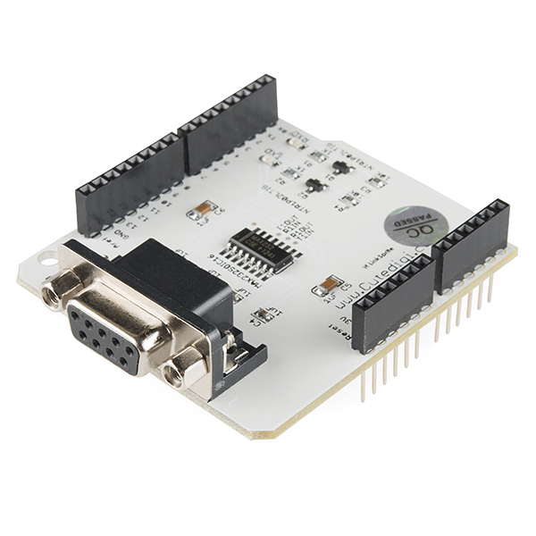
As you know, the Arduino micro controller only has a USB port and a TTL UART interface, so if you need an RS232 port directly connected to your Arduino, look no further than the RS232 Shield.
The RS232 serial port used to be the standard connection for most peripheral ports on PCs, but now the port is primarily used on industrial equipment and automation prototyping, with the RS232 Shield and its DB9 connector, you can now easily access those elements straight from your Arduino.
- Schematics
- Datasheet (MAX232)
- Product Wiki
RS232 Shield Product Help and Resources
Core Skill: Electrical Prototyping
If it requires power, you need to know how much, what all the pins do, and how to hook it up. You may need to reference datasheets, schematics, and know the ins and outs of electronics.
Skill Level: Rookie - You may be required to know a bit more about the component, such as orientation, or how to hook it up, in addition to power requirements. You will need to understand polarized components.
See all skill levels
Comments
Looking for answers to technical questions?
We welcome your comments and suggestions below. However, if you are looking for solutions to technical questions please see our Technical Assistance page.
Customer Reviews
No reviews yet.
Hello, i used same schematic and same rs232 component (max232 cse + 1240). But when I connect rs232 port to my board then max232 is overheating. i didnt find the problem please help .!!
Didn't work for me. I have a $5 RS232 breakout board that works perfectly. This one appears to have the line for RX and TX swapped in a way that flipping the jumpers will not fully correct. It also does not appear to have enough power to drive some COM ports. My advice is to take a pass on this until they do some redesign. Nice idea. Poor execution.
Pro Tip: To program without having to connect/disconnect this shield, pull the jumper closest to the edge of the PCB ("MRX"). Just make sure you replace it in the correct position!
Note that these jumpers do not appear on the schematic or the picture indicated. Not clear what any of these do.
Review: Not impressed at all, but at least it works.
This board shows up in a neat little box, with unsoldered headers. This is really annoying and the picture here is a bit deceiving. The whole point was to save time and not break out my soldering iron station. Heck, if i knew this, i'd be happy with a bucket of parts -- because it would probably take an equal amount of time anyway. Okay, so fine, i solder it up...causing the beautiful silkscreen flood to turn a golden marshmallow brown around the headers.
The product description brags how it can connect to "equipment and automation prototyping" and implies that it operates as an old computer with a serial port. Great, well, how about just a modem? that sounds simple. Wrong. Not only does this shield sport the wrong gender of DB9, but the transmit and receive pins are swapped! To connect something like a modem (or serial printer, or other serial device), better get yourself a null modem and two Male-Male DB9 connectors. (good luck finding a male-male null modem combo cable). Also, don't bother purchasing the DB9 serial cable on sparkfun with this. It won't do you any good.
The shield mostly fits my Mega, however, the board hits the USB jack before it can make a completely solid connection (although its secure enough to where i haven't seen an issue). The RS232 cable and USB are also very snug with one another. It should fit any other arduino Uno on up, assuming the header pattern is the classic pattern.
And finally, no flow control pins are wired up. Yes, the MAX232 would support it just fine, but it appears that nobody ever thought someone would want this. Thankfully it is not in my application, but I know some other folks who really find this useful.
Can you use the Serial Monitor once this shield is connected to the Arduino?
I need to use this to connect an rfid receiver to my Uno. This is the Rx. http://www.ebay.com/itm/300033606407 Don't I need a short male to male RS232 cable? I can't seem to find one
Will this board work with the Due?
Does this work with the Leonardo? If so, how does it interact with the virtual usb port?
It should work with Leonardo. Leonardo still has the TTL serial feature (and on the same pins, digital 0 and 1) - but unlike Uno the feature is separate from the USB communication with the PC. The sketch code would have to be written with this in mind (basically, use the "Serial1" class instead of the "Serial" class) - the upshot is that, on Leonardo, you'd be able to use this shield and the USB connection at the same time without conflict.
is there the Eagle files as usual? I'm confused with some boards having those files and some without? why's that?
If it's a board that we make in-house, we will post the Eagle files. For boards we source externally, the manufacturers do not always provide the full Eagle files, such as this.
I'm confuse about the schematic. They are using a P-Mosfet between the (resistor + Led) and Ground. With this configuration it seems to me the Mosfet will go to an undefined state:
Gate=5V Source=5 V => Mosfet OFF Gate=0V Source=5V => Mosfet ON. But at this same moment the current will start flowing and so S->0V (The same as Drain) Gate=0V Source=0V => Mosfet OFF But if there is no current flowing, S->5V and so the Mosfet will switch to On again. While Gate=0V, the Mosfet will be switching between On and Off...
Does somebody know what am I missing?
From what I know of P and N channel Mosfets, this is a configuration for an N Channel Mosfet, not P (P-Mosfets Souce should be tight to VCC and Drain to the LED)
With the simple shields like this, I for one would prefer there to be a small section of protoboard available, possible tying to the other pins. That way, this would have a justified use rather than just making the arduino one shield taller.
I don't see what there is to complain about with this shield. Engineering tells us to keep bypass caps close but real life tells me a MAX232 circuit works just fine built deadbug style with jumpers running all over. It's just a simple level shifter and the way everything is laid out leads me to believe that the tracks and pin markings are done the way they are to help those just getting started to see how the circuit is built.
That's what schematics are for. If they wanted beginners to see how the circuit was built just by looking at the board, they shouldn't have silkscreened the entire thing. To me, it looks like they spaced everything out simply to justify needing an entire shield for something that can fit inside a DB-9 connector.
I don't understand why the PCB layout is spaced out so wide. Basic EE literacy will tell you that a bypass capacitor should be as close to the IC's power pin as is possible (and it wouldn't hurt to put the MAX232's charge pump capacitors closer either) but this is obviously not the case here. There seems to be a lot of unnecessary copper track length.
The amount of silkscreen on this board is to damn high!