- Home
- Product Categories
- Arduino Shields
- RS485 Shield

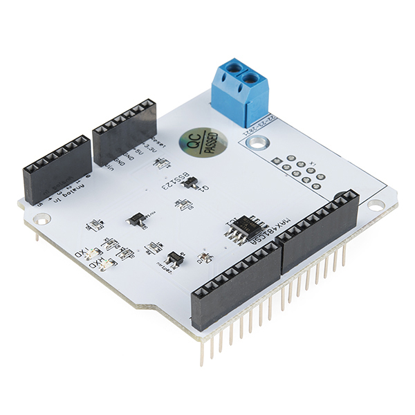
RS485 Shield
Our friends over at LinkSprite have made this nifty little RS485 Shield, now you will be able to have a communication port for your field bus directly connected to your Arduino! Even though the RS485 is sometimes thought as an "archaic" protocol, it will allow up to 32 devices to communicate through the same data line over a cable length of up to 4000ft with a maximum data rate of 10Mbit/s. Those aren't bad numbers!
This shield comes pre-assembled so all you will need to do is just snap it right into your Arduino and get programming.
Note: The shield has an unpopulated footprint for a DB9 connector. Check below if you need to add the connector. Otherwise you can use the screw terminals.
- Schematic
- Datasheet (MAX481CSA)
- Product Wiki
RS485 Shield Product Help and Resources
Core Skill: DIY
Whether it's for assembling a kit, hacking an enclosure, or creating your own parts; the DIY skill is all about knowing how to use tools and the techniques associated with them.
Skill Level: Noob - Basic assembly is required. You may need to provide your own basic tools like a screwdriver, hammer or scissors. Power tools or custom parts are not required. Instructions will be included and easy to follow. Sewing may be required, but only with included patterns.
See all skill levels
Core Skill: Electrical Prototyping
If it requires power, you need to know how much, what all the pins do, and how to hook it up. You may need to reference datasheets, schematics, and know the ins and outs of electronics.
Skill Level: Rookie - You may be required to know a bit more about the component, such as orientation, or how to hook it up, in addition to power requirements. You will need to understand polarized components.
See all skill levels
Comments
Looking for answers to technical questions?
We welcome your comments and suggestions below. However, if you are looking for solutions to technical questions please see our Technical Assistance page.
Customer Reviews
No reviews yet.
Please tell me there is another version of this coming out, why doesn't this thing have the capability of on-board programming like the rest of the shields do? You literally have to take the shield off to program the Arduino and it becomes such a hassle when you are debugging software and not only that, you are making the connector terminals wider. Does anyone know of a way I can rig it up so I can wire the board up to not do this?
*UPDATE: So I figured out how to use this thing to its full potential without interrupting anything with the main serial communication between your computer and the Arduino. So in order to achieve this, you will need a Arduino Mega 2560 because the uno doesn't have this feature. So since the Mega has multiple serial communication slots for serial 1,2, and 3, you have to bend both the Rx and Tx pins 90 degrees so that they don't go into the Rx0 and Tx0 lines and then just jumper wire the Tx and Rx lines from either Serial 1, 2, or 3 pins so that it uses a different serial Rx and Tx so it doesn't interrupt the function of the I/O and communication from the Arduino to the computer. I already tested this and works great now. You can also program the Arduino while the shield is on the Arduino, so you don't have to keep taking it off and on. If anyone has any questions how to achieve this, I will post a instructional download so everyone can do this with pictures.
I recently purchased two of these, and have had success. However, success didn't come without a few pains. I did get communication between two Uno boards - after I connected their grounds together, as most info mentions. Use the standard 'Serial. xxxx' commands. This board uses the hardware serial (pins 0,1), not software serial. In the fine print you'll find that you can not program the Uno with the USB connection without first removing this shield - trust me, it won't work. I now use jumper wires to connect to the Uno so I can quickly disconnect pins 0&1 to program it. The second 'pain', is the error on the Schematic. I wanted to use the DB9 connector, since it has a ground. However, it does not. There is no connection from ground to any of the DB9 pins. I soldered in a jumper wire to correct this. Additionally, the schematic says the data lines are pins 2 and 3. Pin 3 is line B, but line A is on pin 4. Nothing is on pin 2. I was finally able to communicate with an industrial device, and got good data back. UPDATE: The "error" on the schematic is only half an error. The assumption is that you'll be using a female DB9. I was using a male, and so the pins occur in reverse order. I should not have made the assumption...
yes! you cant program the arduino while connected with this shield. The designer should have placed dip switches for programming. This shield utilizes just a converter IC max481 which is serial to rs485 converter. So you also can not connect any other serial device. like bluetooth, gps etc
Can you explain why you can't program the arduino while this shield is connected and how the designer could have made this possible with a dip switch? I'm interested in making something similar and don't want to make the same mistake! Thanks!
Basically this connects to the hardware serial pins on the Arduino. Those are the same pins the Arduino uses to upload the code. You basically end up with things fighting over the hardware line. If you throw in a switch to disconnect the RS485 from the circuitry during upload this solves the issue. Check out our XBee shield, the XBee talks over the hardware line and we threw a switch on there that connects the XBee to either the hardware serial lines or D2/D3. When the XBee is connected to D2/D3 you can upload code to the board, but you can also leave the switch there and talk to the XBee over software serial on D2/D3.
Any one have any code that runs on this? I cant seem to get it to respond. May be a transceiver issue.
What are you trying to communicate with? For industrial equipment, you'll have to set up the serial port similar to what I had to do: Serial.begin (1200,SERIAL_7E1); In my case, 7 data bits, even parity, one stop bit. And, I had to remember to send the check sum with the command string. I'm really new to serial com, and it took me a week of struggling to make it work - but this shield will work. Read my post after this one regarding wiring. Hope you figure it out.
I'm looking at the schematic. I don't believe they got the transceiver control right, you don't just connect the TX data line to the enable line (via an inverter in this case). The RPi version seems to have the same flaw. The transmitter should be enabled for both 0 and 1 bits.
This may work in some cases, but it's way out of spec.
Hi all This shield is compatible with Arduino YUN? I have to use it for Modbus RTU.
This shield uses the hardware serial lines which the Yun uses for the Ethernet bridge. I would recommend just rerouting those two pins for your application and using software serial.
Please provide a RS422 version with jumpers to enable the Rx/Tx pins so those can be wired to whatever pins you choose to use as the UART.
Oh, and both RS485 and RS422 require a common ground reference. I used to think they did not, but upon further reading I found it is needed. So providing a ground terminal would be a good thing even if you don't make a RS422 version.
Hello, could anyone provide me a programming tutorial for Arduino Mega 2560? I would use this Shield with these PING sensors: http://www.dfrobot.com/wiki/index.php/URM04_V2.0_(SKU:SEN0002)
Could anyone please point me in the direction of a good tutorial using this board and a Modbus library. I have been trying to go through the examples from http://code.google.com/p/simple-modbus/ and http://playground.arduino.cc/Code/ModbusMaster but with no luck. I am trying to retrieve information from a modbus slave being a Schneider PM5110 Power meter.
This shield is compatible with Profibus DP protocol?
It would be very good
I am looking to create a simple controller for a BlackMagic Studio Pro Recorder which runs on the RS-422 protocol, does anyone know if this can be converted to RS-422. This only needs limited functionality for our purposes, We all looking to create a controller that will start recording and stop recording and provide the feed back signal so we know if we are recording before a launch.
This only drives to rs485 bus for one state of the transmit data. It won't work unless somewhere else on the rs485 bus it is biased so the other state is the default. And forget about high speed or long lines. I expected better from Sparkfun... Wouldn't be hard to wire the driver enable to another pin of the arduino. Most other designs I have seen use digital pin 2. At least one (mentioned below) uses a retriggerable timer circuit so specific code to control the transmit enable line isn't needed.
Is there a library for Arduino? Or how does one program this things?
How many such shields can you stack on an Arduino. Each shield is just for one serial port right? So if I need to use all 4 ports of Mega 2560 do I need to stack 4 of these shields onto it?
This would be nice to use for making an Arduino based Modbus master device to query a Modbus power meter, shouldn't be to hard to do - right ?
how many wires you need if you want also to send the power supply to another arduino/rs485 shield?
I much prefer my design: http://eco-sustain.org/2013/06/14/testing-version-2-of-the-rs-485-shield/
Although it works for the 3.3V, it can easily be modified for 5V.
I believe that 485 is the protocol that dmx512 is based upon, which would be lighting controllers and the like for music and theatre and the like....
DMX is a 485 protocol. This shield should work for it, but it would have been nice to have a 3 pin header (for shield/ground) and a termination switch.
I use RS485 for robotic systems. this allows the different boards communicate over the entire robot w/ reduced chance of noise issues. I think they should have full and half duplex.
These shields scream for prototype areas.
I was thinking the same thing... I have a blank protoshield I could use with that MAX on a SOIC-SIP (or source the TI part in a DIP) adapter and have plenty of space leftover for another project. Heck, I could populate it as an arduino with 485 built-in! I already know how to put the Arduino bootloader on a blank ATMega 328. ;-)
My only complaint on this as well as the Cute-digi RS485 shields is that they don't have a screw terminal for shield/ground. I have on more than one occasion had equipment that refuses to work without it. Otherwise they work great for industrial equipment and and the Modbus-Master library in particular. It should also be noted that RS485 works great in high noise environments, like those around VFD (variable frequency drive) applications. It would also be nice to see a jumper selectable terminating resistor for those really long runs.
4000ft! cool.