- Home
- Product Categories
- Imaging
- SparkFun Luminosity Sensor Breakout - TSL2561

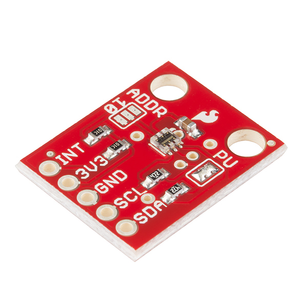
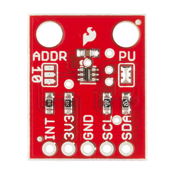
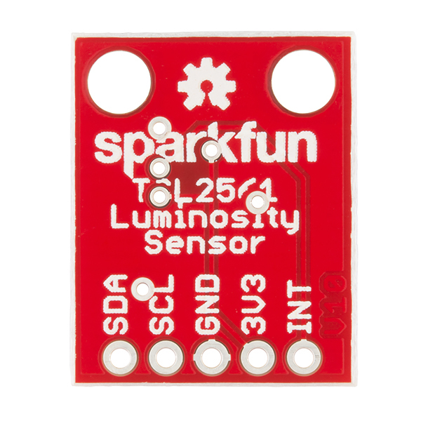
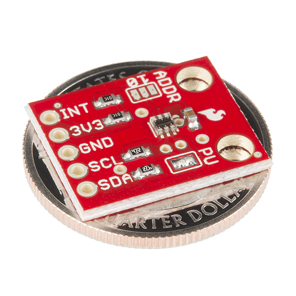
SparkFun Luminosity Sensor Breakout - TSL2561
The TSL2561 SparkFun Luminosity Sensor Breakout is a sophisticated light sensor which has a flat response across most of the visible spectrum. Unlike simpler sensors, the TSL2561 measures both infrared and visible light to better approximate the response of the human eye. And because the TSL2561 is an integrating sensor (it soaks up light for a predetermined amount of time), it is capable of measuring both small and large amounts of light by changing the integration time.
The TSL2561 is capable of direct I2C communication and is able to conduct specific light ranges from 0.1 - 40k+ Lux easily. Additionally, the TSL12561 contains two integrating analog-to-digital converters (ADC) that integrate currents from two photodiodes, simultaneously. Each breakout requires a supply voltage of 3V and a low supply current max of 0.6mA.
- [Schematic](http://cdn.sparkfun.com/datasheets/Sensors/LightImaging/TSL2561 Luminosity Sensor BOB.pdf)
- [Eagle Files](http://cdn.sparkfun.com/datasheets/Sensors/LightImaging/TSL2561 Luminosity Sensor BOB.zip)
- Datasheet
- Hookup Guide
- GitHub (Design Files & Example Code)
- GitHub (Library)
- Product Video
SparkFun Luminosity Sensor Breakout - TSL2561 Product Help and Resources
Changing the I2C address
You can select either 0x39, (default) 0x29, or 0x49 as your I2C address on this board by changing the ADDR jumper. See this photo for instructions.
Core Skill: Soldering
This skill defines how difficult the soldering is on a particular product. It might be a couple simple solder joints, or require special reflow tools.
Skill Level: Noob - Some basic soldering is required, but it is limited to a just a few pins, basic through-hole soldering, and couple (if any) polarized components. A basic soldering iron is all you should need.
See all skill levels
Core Skill: Programming
If a board needs code or communicates somehow, you're going to need to know how to program or interface with it. The programming skill is all about communication and code.
Skill Level: Competent - The toolchain for programming is a bit more complex and will examples may not be explicitly provided for you. You will be required to have a fundamental knowledge of programming and be required to provide your own code. You may need to modify existing libraries or code to work with your specific hardware. Sensor and hardware interfaces will be SPI or I2C.
See all skill levels
Core Skill: Electrical Prototyping
If it requires power, you need to know how much, what all the pins do, and how to hook it up. You may need to reference datasheets, schematics, and know the ins and outs of electronics.
Skill Level: Competent - You will be required to reference a datasheet or schematic to know how to use a component. Your knowledge of a datasheet will only require basic features like power requirements, pinouts, or communications type. Also, you may need a power supply that?s greater than 12V or more than 1A worth of current.
See all skill levels
Comments
Looking for answers to technical questions?
We welcome your comments and suggestions below. However, if you are looking for solutions to technical questions please see our Technical Assistance page.
Customer Reviews
5 out of 5
Based on 1 ratings:
1 of 1 found this helpful:
simple and efficient
It is a very simple device and the library is well written. Needs very little tweaking. I use it to detect quite a low brightness change with high temporal resolution. My first one only started failing after a year of use and abuse (no case and occasional finger prints on the sensors). The second one had a lesser sensitivity and I had to go from 1ms integration time to 2ms to be able to distinguish the two brightness levels in a reliable manner. Overall very satisfied with it but if you use it, try to find a way to encase it in something and it will live much longer and will have better performance.
Is there any benefit of using the interrupt feature of this board? I understand the sensor collects light for a "shutter time" and the interrupt feature allows an interrupt flag to signal when the integration time is finished. Wouldn't the value read from the sensor be updated every integration cycle anyway?
What is the range of this bob? I have tried connecting it to Arduino. When I exposed it to direct sun light, it can detect up to just over 20000 lux. Any other light intensity greater than this lux value resulted in bad data. Any idea? :) Copied from Serial Monitor << data0: 54928 data1: 8727 lux: 22569.30 (good) data0: 65535 data1: 13694 lux: 0.00 (BAD) >> Update < looking into the hookup guide >
I'm looking for guidance in building an enclosure for this and the ML8511 uV sensor ( https://www.sparkfun.com/products/12705) and the ISL29125 RGB sensor (https://www.sparkfun.com/products/12829) combined. My students are building a a light metering device for the school greenhouse and they are trying to determine what transparent material to use. They have decided to test glass, acrylic and polycarb and I am trying to get a sense of what they will find out before thaey test. (it allways pays to stay ahead of your students if you can!) Can anyone tell me how these materials might attenuate the incident light? Does anyone have any suggestions for other suitable "window" materials? Any help would be appreciated.
Since you're just measuring relative light, don't worry about attenuation. Anything that is "transparent" will work, and since the attenuation should be constant over time, you readings will be consistent. If you were trying to measure absolute light levels, then you would need to worry about it. Choose a window based on workability, durability (any chance someone could break glass?) and environment (I think UV damages polycarbonate). I'd go with acrylic.
You should be able to find attenuation characteristics online if you Google hard enough. Since you're only concerned with visible light, I don't think you'll find anything significant. Check Edmund's Scientific for ideas and maybe data.
Dave
Do I need external pull-up (4K7 resistors on module) if I want to connect this module to I2C Raspberry Pi B+?
No, mine works just fine connected directly to a Rapsberry Pi 2's I2C lines with another device on the bus as well.
Hi! I did all the tutorial about this product https://learn.sparkfun.com/tutorials/tsl2561-luminosity-sensor-hookup-guide/all#connecting-the-hardware
and this work fine on my computer. But on my laptop this doesn't work. When i build the exemple there is two errors : 'byte SFE_TSL2561:writeUInt(unsigned char, unsigned int)' does not match any class 'SFE_TSL2561'
Do you have any idea ?
Double check your libraries are nested correctly in your IDE - just ran into this myself yesterday because I unzipped the library files into the wrong spot!
Thanks for answering,
I did it again (juste copy the folder "librairies", which was in the zipped folder, in Documents>Arduino
But that doesn't work
Double check this tutorial, and make sure you're installing the files correctly. It sounds like the libraries just aren't nested quite right for Arduino to read them.
There is a pull request to fix this issue but Sparkfun has not pulled it into the master library yet.
ok i had to change something in the code
the function writeUInt return "byte" in the .cpp and return "boolean" in the .h
I put "boolean" for both of them and now, i can built it
Thank you for your help,
Yes I used it too.
When i move my file it's written " No such file or directory"
I connected this sensor to a raspberry pi B+, and it works. But I did not connect INT to any GPIO, so that the program can not detect the completion of A/D. Even the program could detect the completion, currently, there are no ways (for me, or for my program) to know whether the values available reflects new settings. The program changes those settings (gain and integration time) according to light levels to achieve wide dynamic-range, the program must know when the new settings take effect. The only way is to wait enough after the settings are changed, to confirm the values are not saturated, and to read the values again. No information is provided on the data sheet about that. Are there any solutions?
Did you disconnect pull-up ressistors (4K7) on sensor module?
I disconnected pull-up resistors. Raspberry pi B+ pull up clock and data lines.
Have anyone tried to connect in parallel two of those devices? It works just one of them. I gave them different addresses after solder the paths as the hook-guide says. And i copied the code for one to the other.
Have purchased this sensor as I need to measure lux from 40.000 lux to 0 lux, but I experience same problems as Luform. Firstly one of the internal sensors goes in to saturation resulting in lower measured light, regardless that light is actually increasing. Eventually both internal sensors goes in to saturation. Is there a solution to this or is this sensor just not capable of measuring these light levels?
Actually, does anyone know if setting a new integration time interrupts the ongoing integration? If not, it's hard to know when to read out the data. Supposed it's set to an unknown integration time and I want to use 14ms. If I then have to account for the possibility that it could be running a 400ms integration first, I could have to wait up to 414ms before the correct result shows up. The datasheet doesn't seem to specify this, it just says "when the device is powered up, it will start doing continuous 400ms integrations."
Just so everyone is aware, this device can not handle full daylight without saturating, and the shorter integration times don't help because the limiting factor is the maximum count rate (see Note 6 on p5 of the datasheet), not the maximum value of the readout register. The Sparkfun library doesn't account for this lower saturation level and it will end up looking like the lux value actually goes down in bright sunlight.
If you're talking about the scale factors on page 14 in table 6, the Sparfkun code does incorporate those during lux calculation. As the datasheet notes, those values are proportional to the integration time, so we calculate a scale factor that's correct for both internal fixed and user-supplied integration times. You should certainly be able to reduce the gain and integration time to handle full daylight without saturating. You will lose count resolution, but the magnitude will be correct. If you believe there are errors in the library, you are more than welcome to propose fixes through github.
I think the library is correct except that it looks for 0xffff readouts as evidence of channel saturation. I'll submit a bug fix. But I can't get any measurements above ~40k lux, and in direct sunlight the sensors saturate.
Note that at the top of datasheet page 4, the operating characteristics you're referring to are listed for high gain (X16) mode. I believe that in low-gain mode you have 16X more headroom, but I may be wrong about that.
I double checked by looking at the read-out values of the channels instead of just the lux values. With 100ms integration, 1x gain, the channels increase in value until they peg at 37177. ch0 will saturate first, since it has the highest count rate, at about 40,000 lux. From that point, any increase in light level actually brings the calculated lux down, because the only channel that keeps going up is ch1. When they both saturate at 37177, the calculated lux value is about 805.
this may be just what i have been looking for, but i thought i had better ask before i buy.
I am trying to monitor the intensity of the light emitted by an LED. as the input voltage drops, so does the intensity of my LED output, and I want to quantify this. and for different color LED's.
I have tried some lux meter apps using my tablet, and they seem to work ok for white light, but if i try to measure a very bright green LED, they don't seem to see them (or at a very much lower response). The LED can be so bright I can't look at it, yet these lux meters won't really see the green light.
I have constructed a black chamber with the source LED at one end and the lux meter at the other.
My question : will this Luminosity Sensor work with various segments of the spectrum ?
The lux equations in the datasheet are different for the Chipscale and TMB packages. Which does this use?
Neither, it uses the FN package (which isn't listed in the above datasheet, sorry about that!) Here is a link to the updated datasheet.
anyone know if this sensor can have a maximum limit to be integrated as one wire using multiplexer? I have tried to connect 5 and more but it only work four.anyone have idea why?
Do you know if your TSL2561 Luminosity Sensor Breakout will work with the adafruit libraries: Adafruit_Sensor.cpp, Adafruit_Sensor.h, Adafruit_TSL2561_U.cpp, Adafruit_TSL2561_U.h. I am already using Adafruit_Sensor.cpp and .h for another I2C sensor in my setup. Thanks.
I am trying to compile the example software, but getting the error message 'SFE_TSL2561_example:53: error: "SFE_TSL2561" does not name a type'. The 'SFE_TSL2561 light;' statement is highlighted near the top of the sketch. The downloaded folder was installed in 'Libraries' (on a Mac), and the .h and .cpp files are present. I don't see how the SFE_TSL2561 class is not recognized by the compiler. Any suggestions for how to fix?
That error sounds exactly like the library isn't being recognized.
Did you quit and restart the Arduino IDE after installing the library?
Under your Arduino/libraries folder is there an "SFE_TSL2561" folder that contains the .h and .cpp files?
Does your IDE's "File/Preferences/Sketchbook location" point to your Arduino sketch folder that contains the libraries folder?
If you continue to have trouble, contact our tech support department who will be happy to help get you up and running.
Thanks for your helpful pointers Mike. :-) The example sketch works now.
I think I have one of my 5 sensors broken. I discovered it when tried to attach last 3 of them to my arduino simultaneously (previous 2 worked, attached to other arduinos worked ok). To make it work I removed solder from PU on two of them, and soldered "1" and central on first and "0" and central on other. Let's name:
If i have only A on the line everything is ok, A & B - ok too, as soon as I attach C it starts to heat up and communication to arduino breaks.
I'm not sure but looks like it starts to heat on the headers side.
I tried to measure resistance between different parts on B and C, everything looks similar.
Looks like its output is highly depends on its orientation. Is there any way to make it less orientation light sensor and more diffused light sensor?
Professional lux meters usually have a diffuser over the sensor element. You could try replicating this with a bit of uncolored translucent material in front of the TSL2561, like a ping-pong ball or milk jug. This will also attenuate the light somewhat, so you may need to alter the lux calculations to compensate. (Having a true instrument to calibrate against will make this easier.) Let us know what you try and how it worked!
For sensor located outside value range is 0.05 at night to 400+ in daylight, for sensor in living room that has half of ping pong ball on it value range is 0 an night with lights off to < 1 in daylight
Here is some graphs, third column http://img703.imageshack.us/img703/6563/hbtz.png
At the moment: (night, lights on)
Seems to me that ping-pong ball is not the best option
When uncovered sensor was pointed another way it never reached 1.
According to examples here http://en.wikipedia.org/wiki/Lux I'm very low on my readings.
I was indeed coming to the same conclusion that (even without diffuser) the calculated lux values are much lower than the wikipedia examples. I hope I'll be able to access a professional light meter, to do some tests.
There is a mistake in the sparkfun library - Look for if (gain) { d0 /= 16; d1 /= 16; }
You will get a lot more realistic lux values ….
Thanks for pointing that out. I think they should make a note up there in the product description. May be obvious to someone but wasn't to me, and i even read the datasheet: 1. If you have the gain off then normalize by multiplying by 16. 2. If you have the gain on then no adjustment needed.
I still cant tell if my numbers are correct. I have the sensor in a chicken coop. Nighttime is 0 Lux and Daytime peaks around 60 Lux.
Didn't check the sparkfun libary, but the datasheet fails to notice that the calculations should be made on the values made with the gain on. If not, multiply everything by 16.
Any diffuser will also attenuate the light reaching the sensor, so you should multiply the output by some factor to make up for that. Using your example a quick and dirty way would be to multiply 0.56 by 4,48 to get back to 2.51. (You should really do this with a small bright source like a bare bulb in a dark room, to account for the limited field of view of the bare sensor). The best way would be to compare it to a professional luxmeter and use that to determine your multiplication factor.
Reading the data sheet it appears that this sensor has a illuminance response rate of 400ms, is that right?
There are built-in integration times of 402ms, 101ms and 13.7ms. You can also open and close the "shutter" manually, to implement your own integration time. See the Hookup Guide above for details.
Has anyone tried to use one of these in an Integrating Sphere?
Neat idea! The lux equations in the datasheet assume a bare sensor, so you'd probably need to account for the attenuation somehow. If you try it, let us know how it works. (I think we have some ping-pong balls in the breakroom...)