- Home
- Product Categories
- Other LEDs
- RGB LED Panel - 16x32

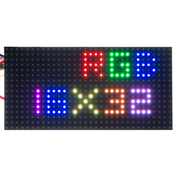
RGB LED Panel - 16x32
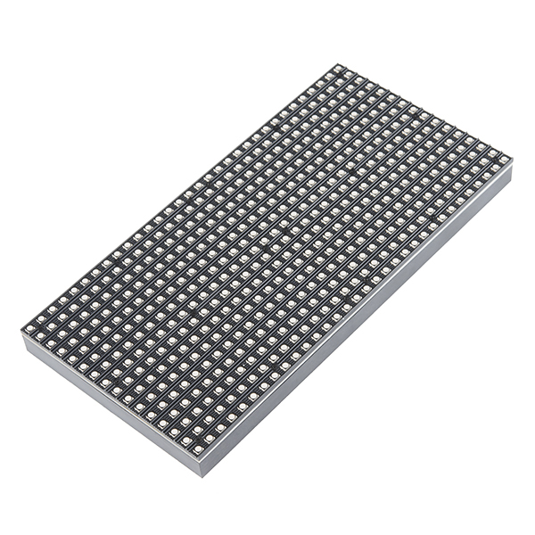
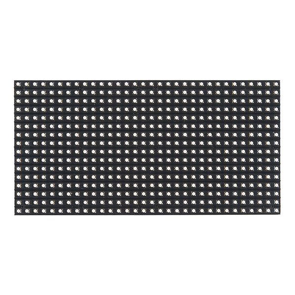
Are you looking to add a lot of color to your project? These large 32x16 RGB LED panels are an awesome place to start. You can create animations, games, or all sorts of other fun displays with them. Yes, you read that right: a 32x16 LED matrix, that's 512 LEDs on a 7.5" x 3.75" board. On top of all that, thanks to two IDC connectors, and a seamless frame, these panels can be daisy chained together to form even bigger LED displays.
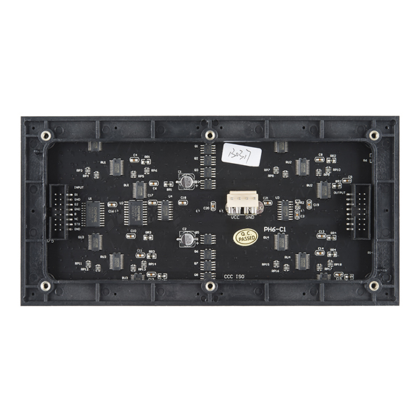
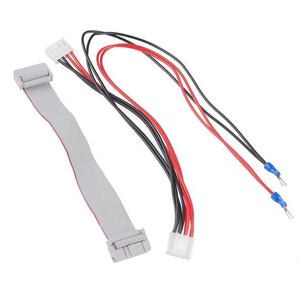
These panels require a regulated 3.3-5V supply for power which needs to be able to source a good amount of current – up to 2A in the worst case. Included with each panel is a 0.15" pitch 4-pin polarized connector power cable which is terminated with both a female polarized connector, and a pair of spade terminals. Needless to say, if you are looking for a large, cheap, and easy to use RGB LED matrix you've come to the right place.
Note: These displays were intended for use with FPGAs and high-speed processors. We've found that 16MHz is about the slowest processor that can drive these adequately. If you want to daisy-chain them together, you will need more speed and more RAM.
- 1x 32x16 RGB LED Panel
- 1x 0.15" Pitch 4-pin Power Cable w/ Spade Connectors
- 1x 16-pin (2x8) Ribbon Cables
- 512 RGB LEDs
- 1/8 Scan Rate
- Dual IDC Connectors for Daisy Chaining
- 3.3-5V Supply Voltage
RGB LED Panel - 16x32 Product Help and Resources
Hackers in Residence: The Sound Visualizer
March 23, 2015
A fun project that uses a Raspberry Pi and a custom Java app to create your own sound visualizer using a RGB LED matrix.
Hackers in Residence: The Sound Visualizer Pt. 2
May 7, 2015
An addition to a previous project, this time using a PC and a custom Java app to create your own music visualizer using a RGB LED matrix.
Core Skill: Programming
If a board needs code or communicates somehow, you're going to need to know how to program or interface with it. The programming skill is all about communication and code.
Skill Level: Competent - The toolchain for programming is a bit more complex and will examples may not be explicitly provided for you. You will be required to have a fundamental knowledge of programming and be required to provide your own code. You may need to modify existing libraries or code to work with your specific hardware. Sensor and hardware interfaces will be SPI or I2C.
See all skill levels
Core Skill: Electrical Prototyping
If it requires power, you need to know how much, what all the pins do, and how to hook it up. You may need to reference datasheets, schematics, and know the ins and outs of electronics.
Skill Level: Rookie - You may be required to know a bit more about the component, such as orientation, or how to hook it up, in addition to power requirements. You will need to understand polarized components.
See all skill levels
Comments
Looking for answers to technical questions?
We welcome your comments and suggestions below. However, if you are looking for solutions to technical questions please see our Technical Assistance page.
Customer Reviews
5 out of 5
Based on 1 ratings:
The ribbon cable I received has the red (pin 1) wire on the bottom v top on the pic in the hookup guide, ie so it connects to OE (pin 15) or gnd (pin 16)?
Packing dept error??
RGB LED Board input pinout information please?
Hello
I wanna ask you if it is possible to connect the RGB LED PANEL - 16X32 to a mbed LPC1768 instead of an Arduino. Thanks
idk if you still need to know, but in case others want to know:
Yes mbed LPC can be used instead of a arduino. This RGB matrix is mostly pretty rudimentary (it is basicly a very large Dot-Matrix display). In fact it is probably more desire to use something as a mbed as that has plenty of memory and processing power to control the screen quickly and do whatever else you want it to do.
This answer applies to any ARM or FPGA device really. mbed, Teensy3.x, Arduino Due.
I'm working on a library for the Teensy 3.1 to drive these panels using DMA. I have an early version that's able to produce 24-bit color with low CPU usage. I expect to have the library along with an Open Hardware adapter board released in about a month. If you're buying one of these panels I suggest you pick up a Teensy 3.1 over an AVR-based Arduino to drive them, the Teensy 3.1 is much more capable.
I'm posting on my project here: http://dangerousprototypes.com/forum/viewtopic.php?f=56&t=6125&p=56311
The labeling on this panel for the Input connector is behind the frame and impossible to see. Also the labeling that is visible (on the right hand side of the connector) starts on a 1 based system (ie: G1, G2) While the hookup guide shows a 0 based (G0, G1). This should be corrected to avoid confusion
Great product! Works very well with the Teensy 3.1. Fast updates. It needs a external power supply but for testing purposes it can be powered by the Teensy alone but due to the low power it only displays a low, dark red color.
Do I need Male/Male or Female/Female for this to connect to the Raspberry pi?
That depends on how you want to connect it. The headers on the board are male, but it comes with a ribbon cable. The headers on the Rasbperry Pi are male, so you will want female on that side (unless you are using some sort of adapter). I would probably go with female to male and connect the cables to the ribbon cable as it might be a tight fit connecting directly to the board.
We have daisy chaiined 5 of these together to make a display using a Raspberry Pi. No luck seeing it outside, just a heads up, unless someone can prove me wrong!
If I wanted to daisy chain panels, can I just to connect the ribbon cable from output/input without changing anything in the source code? I currently have a 16x32 display interfaced with an Arduino Mega with working code based off the RGBMatrixPanel library.
If I only need to display a message in one color (lets say red). Do I have to rewrite over and over again the message in order to maintain it on the screen?
Hello, From Colombia, RGB LED Panel - 16x32 integration Raspberry/BeagleBone Blanck? RGB LED Panel - 16x32 =(equal) http://www.adafruit.com/products/420 ?
This might be of help: the power cable supplied with the panel has two connectors for power (along with the spade contacts at the end). One connector obviously goes in the panel, the spades go to the power supply, which leaves the other connector unused. We (a friend of mine and yours truly) were able to figure out which connection it is: it's a connection made by JST. The datasheet can be found here: http://www.jst-mfg.com/product/pdf/eng/eVH.pdf Digi-key's part number is 455-1650-ND for the angled version.
Incorporate this connector into your (custom PCB?) design and you'll have a clean, non-botched way of powering the driver electronics.
I'm using an equivalent TE Connectivity part in my SmartMatrix Shield Kit for Teensy 3.1. TE 647676-4, Digikey A114290-ND. It looks like your part is about a penny cheaper, but it's always good to have a second source.
You can grab an Eagle footprint off my board, though this part is easy to make from scratch. https://github.com/pixelmatix/SmartMatrix/tree/master/hardware
Do you know which LED video wall drivers this matrix is compatible with? For instance, how about the one at adafruit: http://www.adafruit.com/product/1453
BEWARE: The pins used in the Adafruit library are NOT the same as the ones used in the Hookup Guide. In particular pay attention to the clock and latch pins.
This is extremely bright (will hurt your eyes!). One thing that helped me while developing was placing a thick paper napkin over the panel like a diffuser. This not only lowers the brightness a lot but also makes it diffuse enough so that you don't see the pixels.
Can an Arduino Pro mini run this? If not how about a regular Arduino Pro? The Arduino would not be doing much... It would just be acting as a alarm clock.
I wonder if it is possible to reduce the common brightness. I tried to understand what's happening in the timer interrupt (RGBmatrixPanel.cpp), but I did not succeed. Do I have to trial and error, or has someone a solution for me?
These are very nice panels. Used one in a game of life clock i built: https://synshop.org/blog/sadburger/clock-life very bright and hard to look at without something diffusing the display.
What is the maximum clock rate for the shift registers?
Is it safe to assume the Teensy 3.1 could handle driving this?
Just got done coding on the Teensy 3.1. You cant use the RGBmatrixPanel library, so I made my own. Check it out here: http://www.penguintech.info/2014/teensy-3-1-16x32-rgb-led-panel/
Datasheet please?
we don't have one, neither does the manufacturer. hopefully the hookup guide helps you out a bit.