- Home
- Product Categories
- IMU
- SparkFun 9 Degrees of Freedom IMU Breakout - LSM9DS0

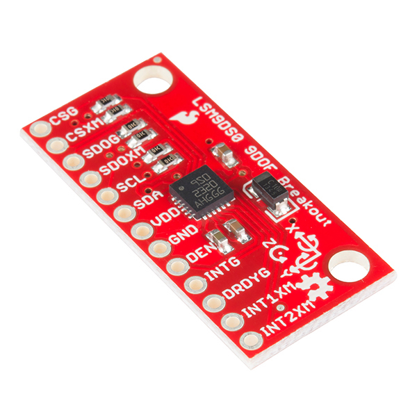
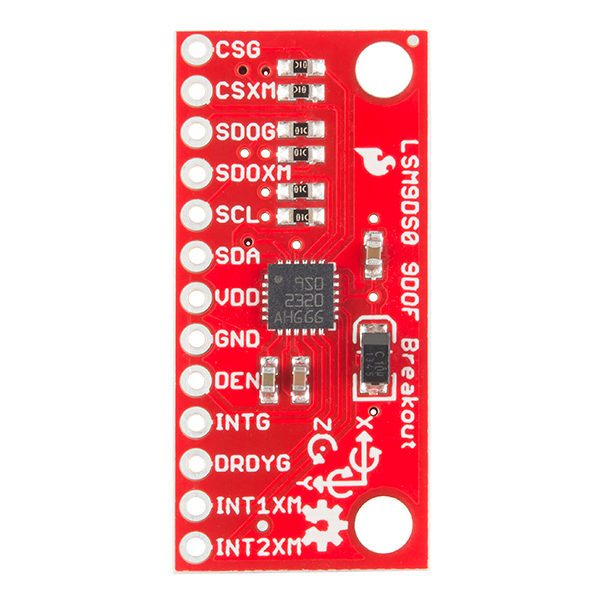
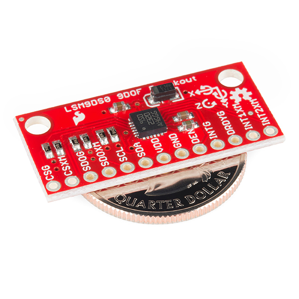
SparkFun 9 Degrees of Freedom IMU Breakout - LSM9DS0
This is the LSM9DS0, a versatile motion-sensing system-in-a-chip that houses a 3-axis accelerometer, 3-axis gyroscope, and 3-axis magnetometer. That's right, 9 degrees of freedom (9dof) from a single IC!
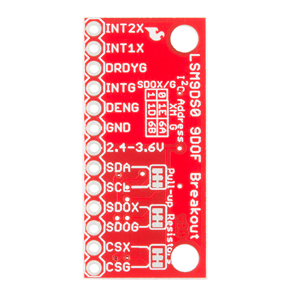
Each sensor in the LSM9DS0 supports a wide range of, well, ranges: the accelerometer’s scale can be set to ± 2, 4, 6, 8, or 16 g, the gyroscope supports ± 245, 500, and 2000 °/s, and the magnetometer has full-scale ranges of ± 2, 4, 8, or 12 gauss. Additionally, the LSM9DS0 includes an I2C serial bus interface supporting standard and fast mode (100 kHz and 400 kHz) and an SPI serial standard interface.
- 3 acceleration channels, 3 angular rate channels, 3 magnetic field channels
- ±2/±4/±6/±8/±16 g linear acceleration full scale
- ±2/±4/±8/±12 gauss magnetic full scale
- ±245/±500/±2000 dps angular rate full scale
- 16-bit data output
- SPI / I2C serial interfaces
- Analog supply voltage 2.4 V to 3.6 V
- Programmable interrupt generators
- Embedded self-test
- Embedded temperature sensor
- Embedded FIFO
- Schematic
- Eagle Files
- Datasheet
- Hookup Guide
- GitHub (Design Files & Example Code)
- GitHub (Library)
- Product Video
SparkFun 9 Degrees of Freedom IMU Breakout - LSM9DS0 Product Help and Resources
LSM9DS0 Hookup Guide
February 27, 2014
How to assemble, connect to, and use the LSM9DS0 -- an accelerometer, gyroscope, and magnetometer all-in-one.
Core Skill: Soldering
This skill defines how difficult the soldering is on a particular product. It might be a couple simple solder joints, or require special reflow tools.
Skill Level: Noob - Some basic soldering is required, but it is limited to a just a few pins, basic through-hole soldering, and couple (if any) polarized components. A basic soldering iron is all you should need.
See all skill levels
Core Skill: Programming
If a board needs code or communicates somehow, you're going to need to know how to program or interface with it. The programming skill is all about communication and code.
Skill Level: Competent - The toolchain for programming is a bit more complex and will examples may not be explicitly provided for you. You will be required to have a fundamental knowledge of programming and be required to provide your own code. You may need to modify existing libraries or code to work with your specific hardware. Sensor and hardware interfaces will be SPI or I2C.
See all skill levels
Core Skill: Electrical Prototyping
If it requires power, you need to know how much, what all the pins do, and how to hook it up. You may need to reference datasheets, schematics, and know the ins and outs of electronics.
Skill Level: Competent - You will be required to reference a datasheet or schematic to know how to use a component. Your knowledge of a datasheet will only require basic features like power requirements, pinouts, or communications type. Also, you may need a power supply that?s greater than 12V or more than 1A worth of current.
See all skill levels
Comments
Looking for answers to technical questions?
We welcome your comments and suggestions below. However, if you are looking for solutions to technical questions please see our Technical Assistance page.
Customer Reviews
4.8 out of 5
Based on 4 ratings:
2 of 2 found this helpful:
Appears to work very well
Am using the 9DOF with a Teensy 3.1 and am quite pleased with the performance. I'm using the 3 ready signals provided by the 9DOF to generate interrupts on the Teensy so I don't tie the Teensy up waiting for data. I'm using the Mahoney algorithm to calculate Quaternions which require 235 usec per calculation on the Teensy. The Madgwick algorithm requires 355 usec, both running the Teensy @72mhz. Should make a good base platform for a flight controller.
Solid unit
SF provides a good amount of support for this board which was nice to have when getting this thing up and running. I have yet to do a lot of analysis on the output, but will make sure to do so when I have.
I ran across a discussion thread at the ST.com forum complaining that no one could read (get anything but zero from) the temperature sensor. I added an edit of the temperature sensor to the Sparkfun GitHub sketch and sure enough, I also get zero for the temperature registers 0x05 and 0x06. That is the result using the Sparkfun breakout board. Yet with a breakout board from NorDevX.com, I am able to read the registers, which give 16 or 17. The data sheet says 8 LSB per degree Centigrade but no info on the intercept. If I assume 21 degrees as the intercept, I get a reasonable temperature of ~23 degrees, when the (independent) DS3231 RTC says 22.25. OK, two questions: why does the Sparkfun board return a zero temperature count and what is the proper offset for the temperature sensor?
Anyone else have trouble reading the temperature?
By default the temperature sensor is disabled. Did you enable it by setting the TEMP_EN bit to 1 in the CTRL_REG5_XM register?
Yes, that is the only way I would have been able to read a non-zero temperature from the NorDevX LSM9DS0 breakout board. However, I could only get zero from the temperature register of the Sparkfun device using the exact same sketch. Check the .cpp file in the Sparkfun LSM9DS0 breakout repository on github and you will see the TEMP_EN bit is enabled now by default. Using this sketch, can you read the temperature from a Sparkfun LSM9DS0 breakout board? Is there an error in the sketch?
If you're seeing this issue reading temperature after setting TEMP_EN, email techsupport@sparkfun.com and we'll get you taken care of.
removed
I was able to get MPU-9150 filter update rates of 1000 Hz without the magnetometer reads on the 3.3 V 8 MHz Pro Mini and 165 to 250 Hz with magnetometer reads at a 10 Hz rate. This is all with direct data register reads; i.e, without reading from the DMP, of course. I wonder how the filter update rates depend on 1) the specific filter, i.e., Kalman vs. Madgwick, and 2) the speed of the microcontroller's processor? I measure about a 50% speed up in the filter update rate with the Mahony sensor fusion algorithm versus the Madgwick. I guess I'll try both using the below sketch with a 16 MHz Uno and see if the times change...
Something that would be interesting would be to put those two filters into RTIMULib as alternatives to the (highly unoptimized) Kalman filter that's there currently.
I was going to copy your Kalman filter to do a timing test on the Pro Mini. Are you saying it would be better to wait for a better optimized version? Is the optimization straightforward, like reducing the number of operations, or is there more to it?
The current performance of the Kalman on a Pro Mini would be far inferior to the highly optimized alternatives (on the other hand, it does seem to perform nicely on the Pi, even if it is wasteful). Now that the RTIMULib drivers are in a reasonable state for 9-dof operation at least, I will take a look at stripping down the Kalman. This is exactly what RTIMULib was designed for - to make filter (and driver) development, testing and tuning easy to do. A lot of things are getting multiplied by zero in the Kalman so there's a fair bit of waste. It's not so much of a problem on the Raspberry Pi which has pretty decent floating point performance. The problem there is getting the data through the OS. It's the opposite to a bare metal microcontroller where it's easy to get the data but there's less processing power.
I appreciate the info on the Kalman filters. I took a look at the library and I think I could adapt it to a simpler Pro Mini sketch. I also found a nice write up on Kalman filtering and might take a crack at constructing one from scratch. I did manage to get the MPU-9150 sketch running on a 5V 16 MHz Arduino Uno but the magnetometer data wasn't right. Maybe the magnetometer on the MPU-9150 isn't 5 V logic tolerant? Anyway, I noticed that the filter update speeds roughly doubled, so I take your point that processor speed likely dominates over the details of any one kind of filter.If you succeed in optimizing the Kalman filter I would like to try it.
Ok.
Done.
I've been working on constructing a full IMU motion-capture suit from these sensors and your arduino coding has been a great help! Do you have any advice on how to convert your code to work with multiple IMUs? I will be using the PCA9509 Level Translator to handle the I2C bus and prevent my Arduino from reading from the same device address. My Arduino will be sending a digital high to connect the I2C bus to a particular IMU while sending a digital low to every other IMU to disconnect them from the main bus. At the moment I'm working on deconstructing the included cpp file and handling everything within the Arduino coding since I'm not sure how to adjust the cpp for multiple devices. I would rather have the Arduino coding alert the cpp file that I want to use a particular address/device, or have the cpp file run for one device, then the next and so forth.
Connecting together supply pins for core and I/O was a really bad idea. Seriously, guys, now I have to use the level shifter to interface your breakout to my project with 1.8V I/O voltage.
I'm having issues configuring the gyro. The Gyro outputs jump all over the place at default values. When i set CTRL_REG2_G "High PASS filter mode config" from the default 00 "Normal (Reset reading HP_RESET_FILTER)" to 10 "Normal" it seems to stabilize. What is the difference between these settings?
What is the mass of the breakout board unit?
My apologies if I am missing the info in the docs.
I'm using 5 of these sensors connected to an arduino with SPI. I'm having a problem with the library.
I can only initialize 2 instances of LSM9DS0 object. If I declare and initialize more than 2 instances, my arduino completely stops functioning and prints garbage.
Could I be running out of memory? or would this be related to the library?
I'm looking to use this with my robot and ROS. Does anyone know where I can find the covariance of the sensors? The datasheet doesn't seem to have anything.
I've been trying to configure the accelerometer interrupt to work for a few hours now. I'm a bit confused about how to get INT1XM to trigger properly. The data sheet is somehow a little bit weak regarding how it works. Ca you please show an example? I've been studying the library and tried to change the setup of CTRL_REG[0-3]_XM without any significant results. If possible, please post a simple example of the setup.
Best regards, Fredrik
9 Degrees of Freedom IMU Breakout - LSM9DS0 There is 6 degrees of freedom (3 linear degrees and 3 rotation). NO MORE degrees of freedom can be!
This is common shorthand for motion sensors, even though it's not technically correct. The extra three "degrees of freedom" are actually just absolute rotation via the magnetometer. In my experience something marketed as a "6-DOF" sensor will only have linear and rotational acceleration.
Hi guys I'm new to the whole IMU business. If I'm trying to gather information from 3-4 different IMUs and send it over a serial bus to a computer, and I need that computer to get a total sampling frequency of 1000Hz for the control algorithm to work with, do I necessarily need a microcontroller or is it possible to bundle and send the data with a specific chip?
Also, how big is the data bundle that a measurement/sample would have to carry? Say, per DOF, ballpark number? I can't quite figure it out from the Datasheets, they only show the normal SPI/I2C frequencies instead of more detailed information on the data size.
Cheers
Hi,I am trying to establish I2C communication between this sensor and the MSP430F5529. I am using energia for loading the program in the master. The problem is when I am trying to read data from sensor after initializing all the sensor, I am not getting any data. But When I am trying to read data without any initialization of any sensor, I am getting data. While getting data,If I moved the breakout, the data didn't get changed.Do anybody here have the same experience like me before?
The Gyro and the Accelerometer have the same Data Out registers, so what is the procedure to distinguish between them?
Each of two devices (1) gyro and 2) accelerometer/magnetometer/temperature sensor) has a unique device (I2C) address. That is how each read to and write from common registers are distinguished. I agree, this is a little unusual; Invensense does it differently, for example.
Worked perfectly for our group-project! Though I am having trouble I'm having trouble both finding and creating a Fritzing part for my Fritzing Diagram. Since time is running out (I need to hand this in soon) I wanted to ask you if you've got the fritzing file and if you could share it through a link in a reply or in your LSM9DS0 Hookup guide? I see you've made a Diagram using the part in the hookup guide, so I hope you still have it?
Thanks! Glad it worked for you.
I just threw the fritzing part up into our Fritzing Parts GitHub repo. It's in the Products/Sensors folder.
I copied the Wire.h readBytes/writeByte routines for another sensor and got bit by not understanding the differences between the MPU9150 and the LSM9DS0. Along the way, I got some good suggestions for improving the existing Sparkfun LSM9DS0 sketch. Please take a look at the forum discussion here: http://forum.pjrc.com/threads/21680-New-I2C-library-for-Teensy3/page5 As embarrasing as this is for me, I think there are some good lessons for anyone using the Wire.h library.
Thanks for such an easy to use library. Also, the sensor data sheet is easy to understand despite its somewhat perfunctory descriptions. I created a sketch to compute filtered quaternion representations of the sensor frame relative to the fixed Earth frame using open-source Madgwick or Mahony 9DoF sensor fusion filtering and can get filter update rates of between 125 (Madgwick) and 165 (Mahony) Hz using a 3.3 V Pro Mini operating at 8 MHz. This is not too much less than the proprietary Digital Motion Processor on-board the MPU 6050 and MPU-9150. The sketch and (slightly) modified library can be found at https://github.com/kriswiner/LSM9SD0. I am going to try the sketch with MPU-9150 accelerometer, gyro, and magnetometer DMP outputs to make a more apples-to-apples comparison. I still do not know exactly how to configure the LSM9SD0 registers to latch the gyro and accelerometer data ready interrupts via the DEN_G function. Maybe an e-mail to ST Microelectronics is in order. Lastly, can we get a version of this breakout board with a square footprint with pins on opposite sides? This would be much more convenient for protoboard mounting applications. Thanks again for a great product!
Such a breeze to set up! Thank you for the hookup guide and clean design.
Hey, if anyone's interested, I think its more fun to see the output graphed than printed to the console, so I modified the "Simple" example that SparkFun provided, to plot the 9 output channels using a processing sketch. Code is here: https://github.com/dahart/arduplot_lsm9ds0_example
stacking three of these in parallel with different ranges looks like it would do a pretty good job of balancing the noise from one and getting much larger accurate range.
I have been studying the library and I think there might be a couple of problems. Where is the twos-complement check (MSbyte > 0x7F) on the raw 16-bit data? Do the scale range algorithms return the correct resolution settings for aRes for +/- 16 g acceleration (10/32768 instead of 16/32768) and for mRes for 2 g scale (0/32768 instead of 2/32768)? Maybe I am mis-interpreting the syntax...
Thanks for checking out the library! I'm not sure I see what you're talking about on the scale algorithms. Is it this line you're looking at? Those should be dividing the correct numbers in, but the shorthand if could be what's confusing.
The two's complement is taken care of by the variable typing, the bit pattern of the combined low and high bytes should remain the same. It works, but looks lazy. I'll see about making it more clear.
Yes, that's the line and the corresponding one for the lowest magnetometer resolution setting. Thanks for the wiki pointer; I had never seen that shorthand before, now I get it.
Are you saying that specifying the signed integer type somehow does the two's complement conversion automatically? That would be convenient!
Thank you Sparkfun for another 9DOF solution for the Arduino! The tutorial and library are very clear and I am looking forward to augmenting the latter for quaternion and compensated roll/pitch/yaw output for various 'round-the-house projects. I have tried to make use of the MPU6050 but have temporarily given up in frustration. Yes, I bought cheap GY-521 breakout boards, but I keep getting -x-motion interrupts and can't seem to consistently set the accelerometer and gyro ranges. Plus, there is the entire issue of how to use the DMP. The point is the MPU6050 is poorly documented and Invensense is, shall we say, less than forthcoming for the individual user. I hope to have a more productive experience when my LSM9DS0 arrives in a few days.The gyro has a maximum ODR of 760 Hz, plenty fast for most applications. I expect this board will work fine in a quadcopter. I'll let you know in a few weeks. In the meantime, I have found a document that sheds some light on the DEN_G function: http://www.st.com/st-web-ui/static/active/en/resource/technical/document/design_tip/DM00067982.pdf.
Thanks! Awesome find. Let us know how it works out for you.
Any plans on stocking the bare chip? Would be nice for own projects/PCBs.
Does anybody know at what frequency the Gyro sensing masses oscillate? I checked the datasheet, but did not find this data. In the past the ST's gyro were not good for quads and helis due to the low frequency of oscillation so most of the control boards use Invensense sensors that have 27 KHz - 33 KHz oscillation rate for gyros.
I am curious whether this sensor is applicable to quads and helis.
Nice
Both the InvenSense and ST part have some issues...
Check out http://www.openshoe.org/ Those AD parts are great - expensive tho:
http://www.analog.com/en/mems-sensors/mems-inertial-measurement-units/products/index.html#iSensor_MEMS_Inertial_Measurement_Units
I agree, the fifo interface for accel/gyro/mag is clean.
What performance specs worse than the 9150 caught your eye xkcd...?
Huh. The performance specs on the gyro and accelerometer for the LSM9DS0 aren't nearly as good as the specs for the MPU-9150. That being said, it looks like ST Mirco made the communication interface much easier to work with than the patchwork job done by InvenSense on the MPU-9150.