- Home
- Product Categories
- Modules
- GPS Receiver - GP-20U7 (56 Channel)


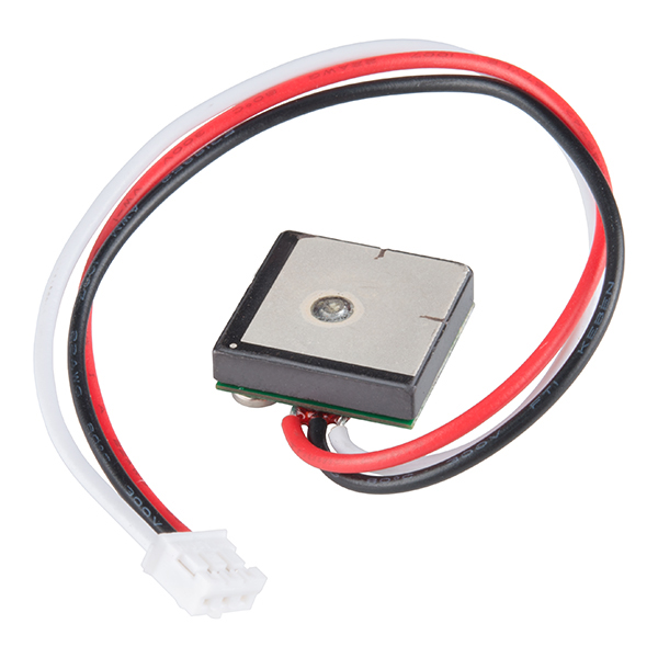
GPS Receiver - GP-20U7 (56 Channel)
The GP-20U7 is a compact GPS receiver with a built-in high performances all-in-one GPS chipset. The GP-20U7 accurately provides position, velocity, and time readings as well possessing high sensitivity and tracking capabilities. Thanks to the low power consumption this receiver requires, the GP-20U7 is ideal for portable applications such as tablet PCs, smart phones, and other devices requiring positioning capability.
This 56-channel GPS module, that supports a standard NMEA-0183 and uBlox 7 protocol, has low power consumption of 40mA@3.3V (max), an antenna on board, and -162dBm tracking sensitivity. With 56 channels in search mode and 22 channels "all-in-view" tracking, the GP-20U7 is quite the work horse for its size.
- 56-Channel Receiver (22 Channel All-in-View)
- Sensitivity : -162dBm
- 2.5m Positional Accuracy
- Cold Start : 29s (Open Sky)
- 40mA @ 3.3V
- 3-pin JST Terminated Cable* 18.4mm x 18.4mm x 4mm
- Datasheet (GP-20U7)
GPS Receiver - GP-20U7 (56 Channel) Product Help and Resources
GPS Differential Vector Pointer
May 31, 2016
Use GPS to have two objects, a base and a target, point towards one another. This can be used to aim a directional antenna (or in the case of this project, a laser) from one object to the other object at a distance that is only limited by your ability to provide the base station with the target's GPS location.
1 of 1 found this helpful:
PPS LED and Functionality
This module does not have PPS functionality. There is silkscreen indicating that an LED could be added but not for this specific model. This PCB board design is shared with a different module that does have PPS functionality.
Core Skill: Programming
If a board needs code or communicates somehow, you're going to need to know how to program or interface with it. The programming skill is all about communication and code.
Skill Level: Rookie - You will need a better fundamental understand of what code is, and how it works. You will be using beginner-level software and development tools like Arduino. You will be dealing directly with code, but numerous examples and libraries are available. Sensors or shields will communicate with serial or TTL.
See all skill levels
Core Skill: Electrical Prototyping
If it requires power, you need to know how much, what all the pins do, and how to hook it up. You may need to reference datasheets, schematics, and know the ins and outs of electronics.
Skill Level: Competent - You will be required to reference a datasheet or schematic to know how to use a component. Your knowledge of a datasheet will only require basic features like power requirements, pinouts, or communications type. Also, you may need a power supply that?s greater than 12V or more than 1A worth of current.
See all skill levels
Comments
Looking for answers to technical questions?
We welcome your comments and suggestions below. However, if you are looking for solutions to technical questions please see our Technical Assistance page.
Customer Reviews
4.3 out of 5
Based on 38 ratings:
8 of 8 found this helpful:
Works well. Easy setup and operation
I'm using this as a replacement for a much earlier generation GPS engine/antenna. Sat acquisition time for this unit is very fast in comparison and a wealth of data is provided over the one-wire (two counting the gnd) serial port interface. The unit is also significantly more sensitive (as well as being about 1/2 the area) as well. The only potential gotcha to watch for is many or most older generations use a default 4800b setting for serial communications. This unit has a default of 9600. You can change the setting of the unit by uploading (over the same single wire used to RX data) or more simply - just change the Arduino (if thats what you are using) sketch code to initialize the serial port to 9600b. I ordered two more of these useful, high-performance units..
1 of 1 found this helpful:
I am happy, but......
I bought several of these modules. I have been testing them on a pcDuino, tied into /dev/ttyS1. I have written my own programs to parse the NMEA messages and to update a Google Map. The module works well, except that I find it does not seem to register movement very quickly. I have the pcDuino running on a Voltaic battery and am using a hotspot to provide mobile power and connectivity to the database server. It seems like it eventually catches up to my new location, but doesn't register along the path as I would like.
2 of 2 found this helpful:
Extremely Good
The first time i plugged it in it was able to draw a dot in google maps that corresponded to the very room of the house i was in within 5 seconds! for 15 bucks it's a great deal. Now it keeps track of where my cat is.
2 of 2 found this helpful:
Works here in Paris, here is the code
Used with a Raspberry 4.4.8, GPS TX port on RPI RX port, here is the python code :
import serial import sys ser = serial.Serial(port='/dev/ttyS0', baudrate=9600, timeout=None,parity=serial.PARITY_NONE, stopbits=serial.STOPBITS_ONE,rtscts=False,xonxoff=False,dsrdtr=False) while True : try: data=ser.readline() print data, except: print "Unexpected error:", sys.exc_info() sys.exit()
which gives : PRMC,1$GPRMC,183902.00,A,4852.08237,N,00238.17086,E,0.101,,140317,,,A75 $GPVTG,,T,,M,0.101,N,0.187,K,A2D $GPGGA,183902.00,4852.08237,N,00238.17086,E,1,10,0.80,40.2,M,46.2,M,,66 $GPGSA,A,3,29,31,25,26,02,14,21,12,05,23,,,1.31,0.80,1.0405 $GPGSV,4,1,13,02,18,042,25,04,43,294,30,05,06,077,30,12,12,101,29*70 and so on... So long chaps
4 of 4 found this helpful:
This little chip is amazing.
Wow, this was a great deal. It worked really well too. I hooked it up to my arduino 3.3 volt power output, ground, and the rx pin on my arduino and downloaded the example serial communication sketch to the arduino board. I had it spitting out nmea 0183 sentences to the serial monitor in less than 5 minutes. I just need to find an application to use it in now. There is also an arduino nmea parsing library that I need to try out, but the chip itself is really great and couldn't be easier to use. It was so sensitive that it even worked indoors (except in my basement).
7 of 7 found this helpful:
Who would have thought you could have a bin of GPS 'just in case?'
If you don't need configurability or a quick update rate this is a no brainer. It works really well, and it only costs $16. Crazy. I agree that the plug seems unnecessary. I almost feel like I should give it 5 stars, especially given the price, but I wish that the extra two pads that aren't broken out weren't gooped over. I also wish there were reasonable documentation for it (without that the rx pin is pretty useless anyway, PPS would be handy though; perhaps I'll scrape off the goop). I'm testing it side by side with the $50 venus module plus the $13 embedded antenna, and the sensitivity on this little beast is better. Only 1 Hz though. I'm going to buy a few for the drawer.
2 of 2 found this helpful:
Mostly good, breaks a price barrier
Finally, a sub $20 GPS receiver with integrated antenna! Don't know why the UP-501 isn't made any more. This comes close to being a replacement. Similar specifications, slightly smaller, same convenient 3.3 Volt supply. But you give up quite a bit: configurable baud rate, configurable update rate, 1 Hz pulse signal, 0.1 inch pin header, separate supply and battery pins (the 501 could be put into a low power state then warm-started). Some of these cons might be fixed with better documentation. And I'm wondering how many buyers actually need the connector this ships with - how about $13 without the wires/connector?
2 of 2 found this helpful:
Good construction, works, and is inexpensive!
Well built and needs only power to function.
When powered up the module quickly started outputting correct data (ie, the 29s cold start spec seems likely to be accurate). Power spec is accurate too. Output data rate is 9600 baud (8N1) serial. Sentences the module sends as configured "out of the box" are: GPRMC, GPVTG, GPGGA, GPGSA, GPGSV, GPGLL (which is also what the datasheet says). An RXD pad is present on the module, as well as what appears to be a 3V button cell.
Absolutely trouble free, works per the datasheet, and overall very impressive capability for the price.
1 of 1 found this helpful:
Plug and Play
It works inside and outside. Very easy to integrate. Just add some code!
1 of 1 found this helpful:
Great economy GPS
I have now built 2 projects with this product. I am pleased with its performance. Since I am using them to display GPS information to a human, the once per second update is just what I wanted. I don't miss the lack of a way to configure the unit. I did have trouble using it on a 12Mhz Arduino using SoftwareSerial, but it worked great on the hardware serial port. Seems to need a 16Mhz Arduino for it to work well with SoftwareSerial. I am using canned library microNMEA to extract data (it is available on github). The price is real nice too!
1 of 1 found this helpful:
Awesome little unit!
This little thing has treated me very well. For the price, I haven't come across anything of similar value. Sure, it only comes with the output wire, so there's theoretically no changing of the standard 1Hz output rate (or other customizations) but for most of my projects, this is just fine. I ended up ditching the connector right away however and soldering the cables directly. I wouldn't mind stashing a few of these away for times when I'll surely need them :P
1 of 1 found this helpful:
Easy to use
This module is easy to use and decent to learn how to parse NMEA sentences, but it is not very reliable when it comes to actually connecting to a satellite. Good price if you are trying to learn though.
1 of 1 found this helpful:
Great GPS
Great GPS for the money.
Covers the basics for a GPS. A little slow update, but in general great.
2 of 2 found this helpful:
Works well.
This is a neat thing let me tell you. Inexpensive and fun to play with. I interfaced it with an ATmega328p without a library just using assembly and it worked fine for me. Concerning getting a fix indoors, mine didn't want to get a fix but if I'd go outside and get a fix then when I came back in it seemed to hold. Warmup time wasn't horrendous either.
A note to those who may not know, you do not need a level shifter to use this with an AVR. I supplied 3v3 to the GPS and 5v to my μC and connected the signal out of the GPS directly to the μC. This works because 3v3 is a high enough voltage to be considered a logical 1 by the AVR and since we aren't trying to write back to it, all is good.
Also, as a side note, don't forget that this unit updates its data one per second. Plenty fast enough for the playing around I was doing, but for some that might be too slow.
1 of 1 found this helpful:
good performance, bargain price
If you need 9600bps NMEA output without giving up a lot of power, space or money, this is a nifty solution. It was just the thing for my APRS project:
http://mythopoeic.org/tm-d710-internal-gps-de-nf3h/
See above URL for detailed information about bench-testing using a Bus Pirate.
Pro: Tiny, cheap, reasonably quick to get a fix, built-in antenna, low power consumption.
Cons: RX and PPS pins hard to access. 3V3 only. Included wires are about five times as thick as they need to be. JST connector is of limited us.
3 of 4 found this helpful:
a nice GPS receiver, but very fragile wires
A good GPS at a good price.
The TinyGPS++ library works great with this.
My major problem was the JST connector. I needed to put on a different connector and ended up destroying 2 of 3 receivers when stripping the wire for the new connector. The pad on the circuit board just ripped off. (So be very very very careful.)
It takes a short period to acquire satellites and get valid data.
Also note that you should use the SmartSerial driver and the smartDelay code from TinyGPS+++ so that you don't get checksum errors and buffer overflows. (This showed up for me as no long/lat/altitude - even though I got valid time data.)
1 of 3 found this helpful:
I don't get use able NMEA data
Hallo!
I bought this GPS Modul for my Electron from Sparkle (also tried it with an Arduino Mega) and I don't get a use able NMEA data and I don't know what I am doing wrong. Maybe someone can help me with this problem...
Best greetings Stefan
Shoot us an email - https://www.sparkfun.com/technical_assistance Thanks
1 of 4 found this helpful:
Not working at All !
I am not feeling good about this product. I bought 2 of them and both are not working. First 2 days it worked fine but not any more. I was very excited but not any more. A lot of issues.
Handy Device
Once I figured out that I needed to use Serial TTL instead of RS232 everything worked exactly as specified in the documentation provided. I primarily use it to update the real time clock in my processor at remote sites. Thanks to Sparkfun support to point me in the right direction.
Great way to get into GPS!
The Receiver is easy to get going and there are many good examples available and several libraries for the Arduino series. The TinyGPSplus is fantastic! A couple of missing pieces: Although there is an input on the device (Rx) there is no documentation that I could find to talk to it. Not wired either. In the documentation, the time returned is shown as hhmmss.sss, but the decimal part is always returned as 00. That's not a big deal for me but a departure from the docs. All in all, a fine entry into the GPS Rx world.
Fast fix, compact size
This little GPS receiver gets a fast lock on satellites even inside a polycarbonate box under a roof. Of course out in the country there is less interference, but I am impressed with its performance. Most of the time the cold start first fix is on the order of a minute or two.
Great Price
I am using this in a Raspberry Pi based NTP server. I added the resistor and LED to the empty locations on the rear and got the PPS signal from the LED. It works great and syncs quickly, even when just pointing towards a window. http://dalimonte.ca/sdalimon/projects/Pi_GPS_Time/pi_time.html
It works as expected with Arduino MEGA
This GPS receiver works great with Arduino MEGA. I connected it to the physical serial pin. I was able to establish connection and get GPS coordinates and data by standard serial communication and TinyGPS library also.
Works great
The most economical unit I've found and it works just fine on RPI2+ using GPIO. Setup in about 15 minutes, outputs NMEA data every second. Python code in Member #912411's review works great too.
Works great
Very easy to get going with this.
Best GPS Unit For the Price
Though many have posted bad things about this GPS as it has no Receive data input so it is not configurable. For a basic GPS Receiver it has worked great for my application and you can't beat the low price.. We purchase them 10 at a time and use them in a low volume product. They lock onto signals fast while near a window so no problems there. The serial data out causes a small problem as it is noisy and detectable by near by receiving equipment. We remove the white wire at the PCB and attach a 100 ohm resister and them reattach the wire after the resister. That resolved the noise issue. Out of about 50 units used, I had one unit fail to lock but no FA was done as it was potted in epoxy inside a 3D printed enclosure. Overall, for the Price and Performance, it is the best I could find.
Works but ....
The unit works well. We connected it to an Arduino Mega, and with some test code, and the TinyGPS library we were off and running with data showing location on the serial monitor. The problem seems to crop up when we set the Arduino with a wireless board, and wanted to just relay the position without attaching a serial monitor. This could be an issue with the tinygps library, but we have not figured out the issue yet. Any input on how to connect this unit without a serial monitor attached to the Arduino, will help .
amazing
Really easy to get to work with my arduino project. A great beginners GPS receiver.
Nice low cost PPS source
I bought this to try as an inexpensive PPS reference for the reciprocal frequency counter I am designing. It works great! My counter has a resolution of 6 digits, and I get a stable reading of 1.000000Hz. The original calibration of the counter was done with a calibrated OCXO, which now gives me extra confidence that the OCXO calibration is good.
To use the PPS output, you have to install an LED and a current limiting resistor, or at least a resistor and short out the LED pads, since the output is open-drain. I used a garden variety 0603 LED, and an 0402 330 Ohm resistor. The LED will light steady when power is first applied, then you will see it pulse after the GPS syncs (takes a couple of minutes for me).
Easy to use!
Very easy to use and accurate. Great product for the price.
Worked like the documentation said it would
No surprises. Follwed the directions for hooking it up to an arduino and had a good gps fix in and 30 seconds insde the house
Extremely easy to get going, great value
This was super easy to get going, and it’s a great value.
This little GPS Rx'er is working just fine in our project!
I do like the compact size of this GPS Rx'er, fits right in with the other components of our project. Does provide good signal recognition and GPS data as expected!
I enjoy working with SparkFun, they provide great technical support and a wide variety of products for us hackers!
Worked well, easy to get running, but took some sleuthing...
This was easy to get up and running, but required a little sleuthing, as the SparkFun page for this device doesn't include any links to the code you need to see the data streaming from the module. Here is a link to the page on the SparkFun site for that information: tinyurl.com/y9kl7mcx
You need to download and install the TinyGPS++ library from the link shown at the top of that section, and then copy and past the code for the "Sketch: TinyGPS Serial Streaming" into the Arduino user interface. Connect the black ground wire to GND on the RedBoard, and the red power wire to the 3.3V pin (NOT the 5v pin. You will destroy the GPS module!). Then connect the white data wire to Pin 8. Connect the USB cable to your computer, open the "Serial Monitor" under "Tools." Compile and upload the code to the RedBoard, and you should start seeing the GPS data streaming on the Serial Monitor window, updating once per second. It takes a minute or so for the data fill out all the fields, depending on how well the GPS module can see the sky. Being near a window, if you are inside, helps. Place the module with the gray antenna patch facing up, and the wire connections facing down. Hope this helps. And... Sparkfun team, you should place a link to the code on the page for this device.
Worked well for me so far
Impressive sensitivity, worked thru my window, facing down toward the table! Wire connections/strain relief doesn't look very robust.
Nice product for the price
Nice and simple GPS for arduinos, working well with every arduino GPS library I have found.
To get started using this with arduino:
Download https://github.com/mikalhart/TinyGPSPlus
Pick the example code you wish to run. Within the .ino file, change #include<TinyGPS++.h> to the location of the TinyGPS++.cpp file in the TinyGPSPlus-xxxx directory. In my case:
include <~/TinyGPSPlus-0.94b/TinyGPS++.cpp>
Change the variable GPSBAUD from 4800 to 9600
Last but not least, change TXPin and RXPin to appropriate values (ie: TXPin is where you have the white wire plugged into your arduino).
You should be able to upload the code and watch the serial monitor output the information.
Here's a sample of the output:
so you have been to to boulder creek near N 107th st and goose haven dr. in boulder colo on 04 dec at 20:02 utc or 1:02 pm this was read off of the RMC line
Close, but no cigar. The information on this page will get you on track. :-)
Thanks, my converter on the smartphone was wrong, when I did it by hand and dumb calculator, I have you at the loading gate of Sparkfun.
Found the answer in Adafruit site (http://www.adafruit.com/products/954) via USB to TTL adapter cable. This solution will cost another $9.00.
I prefer SparkFun's version, https://www.sparkfun.com/products/12977 since it has the connector ends labeled. Same price
Does that PPS pad actually work? Also curious if the RX pad allows control of the module like others are hinting at.
For me, not enough of the cheap GPS modules support PPS, which is critical for some applications of mine.
If you add a resistor and LED it works. I made an NTP server from one and a Raspberry Pi.
The pad next to the PPS label is 3.3V. The LED pad under it is the PPS output. It is open-drain so a pull-up is needed. The LED and resistor make a good pull-up and give a visual sync indication. Photos are here
Did you get/find an answer yet? I'd like to know this too.
Based on this Rx/Tx wiring issue and what you get out of the default data stream, this is either a great deal or a waste of $15. Could someone post some sample data?
Datasheet says that it's 1Hz NMEA-0183 Ver 3.01 via a 9.6K baud serial. NEMA 0183 is an ASCII plaintext protocol that you can find the specifics of by googling around. Here's a wikipeida article on the protocol: https://en.wikipedia.org/wiki/NMEA_0183 , and the data sheet goes into the protocol some as well. The datasheet also specifies that TX is UART Serial Data Output, so I'm led to believe that it's wired properly.
The datasheet also does specify that: "NMEA Output Messages: the module board outputs the following messages..." listing GGA, GLL, GSA, GSV, RMC and VTG. So without input, it should be sending at least those messages.
How does this work with a 3-pin JST and nothing connected to the RX pin (according to the 2nd photo)? From the data sheet, it uses a command-response serial protocol, so I'd expect both TX and RX to be necessary for proper operation.
I read the datasheet and here is what I found:
The module outputs all of these messages: : GGA, GLL, GSA, GSV, RMC and VTG
You get it all. Doesn't say anything about 2 way to command the device.
It boots up, finds the stats and spits out the messages.
Seems simple enough.
Thanks for clarifying. Please consider being less condescending in your responses.
You misunderstand, I meant that I had the datasheet. Not saying you didn't.
It only needs power, gnd, TX.. TX as in, it's sending you the data.
Didn't mean for you to take it the wrong way..
Ugh, the written English language needs separate words for the different uses of read. I also immediately though you meant "Go and read the datasheet", not "I read the datasheet and here is what I found"
yep.. :)
The Tx pin is wired, not Rx, and it'll send out a default information stream by itself. The Rx pin is needed to send it commands, but the skimpy documentation leaves us guessing at what commands will work.
TX pin is data being transmitted out of the GPS?
https://en.wikipedia.org/wiki/Write-only_memory_%28joke%29
GREAT little device! don't forget... it can be used for easy access to date/time, as well as position.
Sadly, the "support" for THIS product UNRECOGNIZABLE as Sparkfun support. (Sparkfun is my regular "go to" source, for many years, because usually they take all the pain out of getting started with something.)
For a simple guide to getting started with it... which is MUCH easier than the only Sparkfun "support" would suggest... see https://wywtk.com/ec/iec/iec217.htm
Can this module be set in air mode Model16 as ublox components can, so that it can be used in a high altitude balloon project?
Can this module be set in air mode Model16 as other ublox components can, so that it can be used in a high altitude balloon project?
How much does it weigh? looking at adding it to a small DIY drone, ran from an ATMEGA328
I checked the datasheet, and it doesn't say.
Does anyone know if this will work for a high altitude balloon application? What is the maximum altitude this is rated for?
So.. This seems like a great little GPS.. I am making a position logger for a cruise I'm going on this weekend, and I've got it set just to record everything into giant NMEA text files, and I'll figure out what to do with it when I get back, but I have one big problem.. There doesn't seem to be a provided GPS sentence that would give me the current DATE.. I can get the TIME from the $GPGGA but there's no DATE! It doesn't send the $GPZDA sentence apparently, so I'm bummed.. I wanted this thing to set the time and name the output files based on the GPS provided date/time, but now I'm going to have to plug it in and make sure it gets the date set at least, so my files are correct.. Does anyone see anything I'm missing? --EDIT -- False alarm... It DOES send the $GPRMC sentence, which also has the date, so it looks like I'm good!!
That being said, sitting here in my house on my workbench, I just turn it on and I get 4 sats and a good fix in just a few seconds. I'm sure it'll be great when it can see the sky!
im getting coordinates about 9 miles away from where i actually am. do i have a defective unit?
GPS tends to be relayed in 2 ways, specifically the last few digits. Basically what I think is happening is that the GPS and your mapping software (Google maps, etc.) are using 2 different coordinate systems. One system uses degrees, minutes, and seconds. The other uses decimal degrees. If you use the incorrect one you tend to be off by about that much (enough to know it is mostly working, but also enough to know it isn't right). Check out this conversion and see if it helps.
Hello. Anybody knows if it possible to connect to 5V the module? because in the datasheet in the last page appears power supply pin 4, 3-5V. Thanks for your support!
Regarding the battery, any information on what kind of battery it is (i.e. rechargable when the device has 3.3V power or just a primary cell)? I saw the comment about it "lasting for several years" (and I know what it's for), but I'm a little uncomfortable deploying a device with this module without knowing more about the battery and its real-world life expectancy. I could not find any information about it in the data sheet.
How does one connect this to say a ESP2866 or Raspberry PI? I didn't see a JST female connector to jump wires.
I snipped the wires and used it on a Raspberry pi with a screw terminal proto top.. Not pretty but it works..
Is there an easy way to remove the red stuff holding the wires in place?
Does anyone know what the red goop is? or a good way to remove it?
I get the following output. I have tried it with an Arduino, an Electron from Sparkle and with a USB to Serial and I always get the same response. I also was outside on a field to test if (maybe it don't get some signal in rooms). Can someone help me with this problem?
hi. I tried using the module with arduino directly l.e 3.3v -> VCC, GND -> GND, RX->TX but i keep getting $GPGSA,A,1,,,,,,,,,,,,,99.99,99.99,99.99*30 and i tried using online nmea converter to convert it but it not working. How can i make it work Note. Am using arduino serial monitor to get the informatation.
Just got this device in and I am trying to determine how you know if the device is powered up and/or if it has a fix. Reviews seem good but the documentation is lacking. It looks to have an LED on it but I am not sure if that LED works. It would seem that would pulse or turn on if the device had power.
Anyone have any idea how good the signal strength is indoors?
Curious if anyone has tried using ublox protocol. Does it expose additional functionality/configuration? Or is it just a binary alternative to NMEA in this application?
Approx a week ago the question was asked if the TX data I/O is 5V tolerant. I do not see any definitive answers.
What is the battery for? How long will it last and what happens when I use it if the battery dies or without a battery?
The button cell is to maintain the almanac and clock while "off". This gives it a starting point to look for satellites the next time it starts up. Basically faster acquisition. The battery should last several years. When it dies (or if you remove it) the receiver will still work fine, you'll just have slower acquisition. Also note that if you use this very infrequently (like more than a month between uses) you may as well not have the coin cell because the clock and almanac will be far enough off to be nearly useless.
SENSITIVE! I tried this thing in my basement lab. 5 feet underground, against a concrete wall, sitting on the bench. Got a good fix. Had my doubts. Put the whole thing inside an aluminum bud box, ungrounded, but not fully closed up. Still had an active fix. It wasn't until I grounded the box that I got an inValid fix flag that I truly believed how sensitive this thing is. Havn't been able to confirm if the course-true indicator works at some speed or not. It reads null when stationary.
Is the Rx pin 5v tolerant? The datasheet is a bit vague.. the electrical specs are 3.6V max, but the Hardware section shows Vcc at 3 - 5 V... Just need some clarification here..
Ublox 7 data sheets indicate a maximum altitude of 50km. But your data sheet says 18km. Is this really a ublox 7 chip?
18km. http://hardware.slashdot.org/story/13/10/01/1337243/bypassing-us-gps-limits-for-active-guided-rockets
I was wondering if this could be hooked up to an arduino and if so what would be required to enable it ? Is there are library already available?
Yes. TinyGPS and TinyGPS++ are both excellent.
Does this work with the Weather shield? What's the difference between this module and the GP-645T GPS Module?
According to the data sheet, only control I/O connections provided. Has anyone checked the possibility of finding an internal signal that can be used to discipline an oscillator to serve as a frequence standard? This would be interesting to know before I buy this item.
The commands that can be sent to the receiver are in the UBLOX 7 protocol mentioned in the description. Of course, this will require soldering a lead to RX on the board. For the protocol, see:
https://www.u-blox.com/sites/default/files/products/documents/u-blox7-V14_ReceiverDescrProtSpec_%28GPS.G7-SW-12001%29_Public.pdf
In my case, I would want to set the serial post parameters to a higher data rate, which is achieved via the CFG-PRT message.
In the pictures and the "datasheet" it shows the RX line, needed for 2-way communication. What is really needed is the commands and the configuration information to change the settings, if desired. No point in 2-way comm if there is no idea on what to do ... unless I missed something?
I suppose the message can be parsed for the relevant information.
Is there an antenna hookup, or is it possible to solder your own on? I'm looking at using this in a car where I want to hide everything away in a nice box in the dash, but from what I understand I would need to leave the GPS exposed somewhere by a window so it can pickup on the satellites, so I would like to have an atenna
This one has the antenna built-in. You could place the whole module in a good spot and run the three wires to it, or consider a GPS receiver like the Venus which has a connector for an external antenna.
It looks to me this product is bargain! If anyone from Sparkfun can hear me, please post a tutorial on how to hook this component to a Raspberry Pi. You'll be shipping hundreds of this product in the upcoming months (hint: Raspberry Pi Zero :-) )
I think the key here is "images are CC BY-NC-SA 3.0", and the actual module for sale & datasheet are for GP-20U? NOTE: GP-20U has both Rx & Tx pins.
CC BY-NC-SA 3.0 is a creative commons (alternative copyright) license code for the image not a part number. Your confusion is warranted because it totally looks like a part number.
How to do you get a "hot start" or a "warm start" with this module? Looks like the module has a coin cell on it.
Does it hold start up data over power down? If so for how long?
So if I wanted TABLE 7 how do I communicate that to this device if the RX pin is not connected? Or to simplify things, does this work with any Arduino or RaspPi libraries?
Thanks for your time
Table 7 defines the fields returned by the GPS in the VTG sentence. According to the datasheet the GPS will transmit all sentences specified in Table 1. Your software just needs to parse the incoming datastream and when it finds Message Id $GPVTG parse the fields for that sentence up to the End of Message characters.
Oh perfect thanks