- Home
- Product Categories
- Distance
- SparkFun Distance Sensor Breakout - RFD77402 (Qwiic)

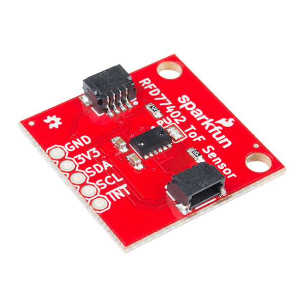
SparkFun Distance Sensor Breakout - RFD77402 (Qwiic)
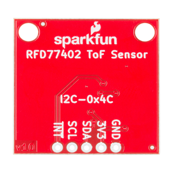
The SparkFun Distance Sensor Breakout utilizes the RFD77402 3D ToF (Time of Flight) sensor module from Simblee to give you the most accurate measurements at short range. The RFD77402 uses an infrared VCSEL (Vertical Cavity Surface Emitting Laser) module to measure the amount of time it takes to bounce off a target. This allows low-cost millimeter readings up to two meters! To make it even easier to use this breakout, all communication is enacted exclusively via I2C, utilizing our handy Qwiic system. However, we still have broken out 0.1" spaced pins in case you prefer to use a breadboard.
Thanks to the RFD77402's 850nm VCSEL and electronic driver and optical receiver sensor, this breakout is ideal for distance measurements ranging from 100mm to 2000mm, 1D gesture recognition, obstacle detection and avoidance in robotics applications, and more! The RFD77402 utilizes an I2C interface that supports a direct 8-bit addressing scheme to access the module user’s register set and an additional 16-bit indirect addressing scheme that is mainly used for debugging purpose or special operations.
NOTE: The I2C address of the RFD77402 is 0x4C and is hardware defined. A multiplexer/Mux is required to communicate to multiple RFD77402 sensors on a single bus. If you need to use more than one RFD77402 sensor consider using the Qwiic Mux Breakout.
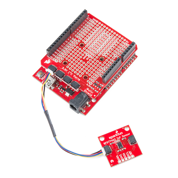
The SparkFun Qwiic Connect System is an ecosystem of I2C sensors, actuators, shields and cables that make prototyping faster and less prone to error. All Qwiic-enabled boards use a common 1mm pitch, 4-pin JST connector. This reduces the amount of required PCB space, and polarized connections mean you can’t hook it up wrong.
Note: CLASS 1 LASER PRODUCT CLASSIFIED IEC 60825-1 2014.
- Operating Voltage 3.3V
- Current 7 mA average at 10Hz
- Measurement Range: ~50mm to 2,000mm
- Precision: +/-10%
- Light Source: 850nm VCSEL
- I2C Address: 0x4C
- Field of View: 55°
- Field of Illumination: 23°
- Max Read Rate: 10Hz (We've seen up to 20Hz in practice)
- 2x Qwiic Connection Ports
- Schematic
- KiCad Files
- Hookup Guide
- Datasheet (RFD77402)
- Arduino Library
- GitHub
SparkFun Distance Sensor Breakout - RFD77402 (Qwiic) Product Help and Resources
Qwiic Distance Sensor (RFD77402) Hookup Guide
April 5, 2018
The RFD77402 uses an infrared VCSEL (Vertical Cavity Surface Emitting Laser) TOF (Time of Flight) module capable of millimeter precision distance readings up to 2 meters. It’s also part of SparkFun’s Qwiic system, so you won’t have to do any soldering to figure out how far away things are.
Core Skill: Programming
If a board needs code or communicates somehow, you're going to need to know how to program or interface with it. The programming skill is all about communication and code.
Skill Level: Competent - The toolchain for programming is a bit more complex and will examples may not be explicitly provided for you. You will be required to have a fundamental knowledge of programming and be required to provide your own code. You may need to modify existing libraries or code to work with your specific hardware. Sensor and hardware interfaces will be SPI or I2C.
See all skill levels
Core Skill: Electrical Prototyping
If it requires power, you need to know how much, what all the pins do, and how to hook it up. You may need to reference datasheets, schematics, and know the ins and outs of electronics.
Skill Level: Rookie - You may be required to know a bit more about the component, such as orientation, or how to hook it up, in addition to power requirements. You will need to understand polarized components.
See all skill levels
Comments
Looking for answers to technical questions?
We welcome your comments and suggestions below. However, if you are looking for solutions to technical questions please see our Technical Assistance page.
Customer Reviews
3 out of 5
Based on 1 ratings:
Does not tolerate ambient light
It was easy to connect and worked well when not exposed to much ambient light. However, even indoors in a brightly lit room it defaulted to a 2046 output making it pretty useless except in well controlled environments. Unfortunately, this is typical of most of the TOF sensors I have tested. I wish vendors would make us aware of these limitations saving us time and money.
Are there 3d models or 2d drawings of the part that I can download? I am trying to use this in a custom robot and need to put the part in a 3d model of it or I need the hole dimensions to model it myself.
Thanks
If there should only be one set of pull up resistors per I2C bus, then why do you (Sparkfun):
1) put the pull up resistors on each sensor/device (of which there can be many) rather than the microcontroller (of which there is only one)
2) close the pull up jumpers by default, requiring all but one to be opened
3) use solder to close the jumpers, requiring tedious desoldering on all but one peripheral? (So much for 'no soldering required')
I noticed that you did #1 (resistors on microcontroller) for the blynk board and #3 (trace instead of solder) for many products, but never #2 (default no pull up resistors). I would assume you have a reason for doing what you are doing but you have been very inconsistent with minor details like pull up resistors, power LEDs (why do some boards need them and some don't?), etc.
I want answers! :)
The Qwiic system has had quite a few features added to it since its inception (like the power LED, which is standard on many recent boards), we put pull-ups on everything because we never know when you'll be using an MCU/Slave that for some reason doesn't have them. We've moved towards trace jumpers on many of the recent Qwiic boards to eliminate production issues, although many old boards still have solder jumpers. Also, you can usually daisy chain quite a few Qwiic devices before running into the issue of too strong of a pullup on your I2C lines (This depends on MCU and cabling) so most of the time you shouldn't have to worry about removing pull-ups.
In short, some of these minor details have changed as we've learned what exactly we want the system to look like. Hope this helps. We also put pull ups everywhere on the chance you're using some 3rd party product without them.
One of the main reasons was microcontrollers may or may not have pullups and we wanted to make sure our I2C boards will plug and play. Whether or not your microcontroller has pullups or not you should be able to plug in the board and just get started, you only tend to start running into problems when you have quite a few (in which case the new trace solder jumpers are the easiest option for change). In other words what Englandsaurus said as well as wanting these to be as easy as possible to start with.
I'm glad I don't have to worry about removing every single pull up jumper/solder, although "quite a few" is vague. There is not much you can change now, but couldn't you have made a separate QWIIC pull up resistor board to put in any circuit that didn't already have a Sparkfun MCU/adapter board with them?
P.S. The power leds are keeping me up at night, literally. They shine through the 3d printed enclosure of my recent alarm clock project.
You're free to make your own boards without LEDs and resistors if you wish.
I know but I choose "QWIIC" for a reason. Despite what I've said, its a great product line.
Easy to setup and use, but I'm seeing +/- 6mm when 250 mm away... so don't expect a solid reading.
What is the object you are detecting the distance from out of curiosity?
I tried it with several different objects to start, but for the final testing I used a white wall. Actually, if you look at your hookup guide, you’ll even see similar numbers in the screenshots there... I just didn’t catch that detail when I was reading it...
Could this be used as a water level sensor, or would the signal just go through the water?
I've seen the Lidar Lite go through glass. Depends on the attenuation coefficient for water at the wavelength, but in general it's not 100% for near ir. I would go with sonar for measuring water level. You could also float a reflector of appropriate material on the surface of the water if you want to use ir or are concerned about the wide beam angle from sonar.