- Home
- Product Categories
- Encoders
- Rotary Encoder - Illuminated (Red/Green)

Rotary Encoder - Illuminated (Red/Green)
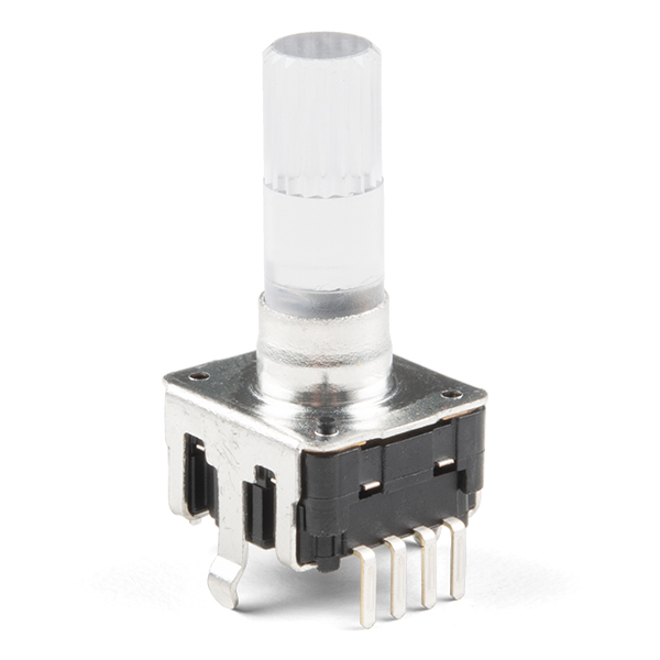
Rotary encoders are used similarly to potentiometers. They're different from potentiometers in that an encoder has full rotation without limits. They output gray code so that you can tell how much and in which direction the encoder has been turned.
This encoder is especially cool because it has a red/green LED built in, as well as a push-button. This version has an updated material that is heat resistant and slightly changed dimensions, but should still work well with our rotary encoder breakout board and the clear knob.
- Switch Travel: 0.5mm
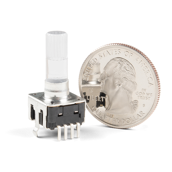
- Shaft Diameter: 6.0mm
- Shaft Length: 18mm
- Vertical Through-Hole Mount
- Red/Green LED
- Pushbutton
Rotary Encoder - Illuminated (Red/Green) Product Help and Resources
Core Skill: Soldering
This skill defines how difficult the soldering is on a particular product. It might be a couple simple solder joints, or require special reflow tools.
Skill Level: Rookie - The number of pins increases, and you will have to determine polarity of components and some of the components might be a bit trickier or close together. You might need solder wick or flux.
See all skill levels
Core Skill: DIY
Whether it's for assembling a kit, hacking an enclosure, or creating your own parts; the DIY skill is all about knowing how to use tools and the techniques associated with them.
Skill Level: Noob - Basic assembly is required. You may need to provide your own basic tools like a screwdriver, hammer or scissors. Power tools or custom parts are not required. Instructions will be included and easy to follow. Sewing may be required, but only with included patterns.
See all skill levels
Core Skill: Programming
If a board needs code or communicates somehow, you're going to need to know how to program or interface with it. The programming skill is all about communication and code.
Skill Level: Competent - The toolchain for programming is a bit more complex and will examples may not be explicitly provided for you. You will be required to have a fundamental knowledge of programming and be required to provide your own code. You may need to modify existing libraries or code to work with your specific hardware. Sensor and hardware interfaces will be SPI or I2C.
See all skill levels
Core Skill: Electrical Prototyping
If it requires power, you need to know how much, what all the pins do, and how to hook it up. You may need to reference datasheets, schematics, and know the ins and outs of electronics.
Skill Level: Noob - You don't need to reference a datasheet, but you will need to know basic power requirements.
See all skill levels
Comments
Looking for answers to technical questions?
We welcome your comments and suggestions below. However, if you are looking for solutions to technical questions please see our Technical Assistance page.
Customer Reviews
No reviews yet.
Wow. I cannot believe the data sheet. The waveforms show the rising edge as going from ON to OFF and the falling edge going from OFF to ON. That can't even be blamed on a bad Chinese to English translation. What were they thinking?
For the curious, the body is 0.3mm taller and the knurled part of the shaft is 0.3mm shorter than the old version. It is otherwise identical.
How much force is needed for the click on the pushbutton? Rotary encoders usually require a lot of pressure to perform the click, how about this one?
In my opinion the pressure needed is not too much nor too little. In other words, easy to press, but not so much that it could be pressed just when trying to rotating it.
But I decided to try and measure it. I got a kitchen scale, and put the encoder on it (with the clear plastic knob) and zeroed out the scale. Then I slowly increased pressure on it till it clicked. Did it several times. Somewhere around 15-16 oz or 450-460 grams is when I felt the click.
Rotary wiring instructions: the 3 pins are A, GRD, B. Use #include <Encoder.h> (look at the examples in there)
I assume that current limiting resistors are incorporated into the LEDs. I read the datasheet (not the best I've seen) but found no reference to these resistors. From the example sketch, it seems the LEDs are hooked up directly to the Arduino pins. --Thanks--
As for the encoder, it works well...
Current limiting resistors are normally built into devices and not the LEDs themselves. Therefore, if it isn't specified, it is because they aren't incorporated in the device.
Luckily, the Arduino boards inherently limit the amount of current they can drive. However, you should still use current limiting resistors because you can still damage the product.
EDIT: Sorry, I didn't realize both posts were by the same user.
I don't think there are built in resistors, I connected +5V to the red diode anode and it was very bright for a very short time ;-) Then it was dead...