- Home
- SparkFun Transceiver Breakout - nRF2401A (Chip Antenna)

SparkFun Transceiver Breakout - nRF2401A (Chip Antenna)
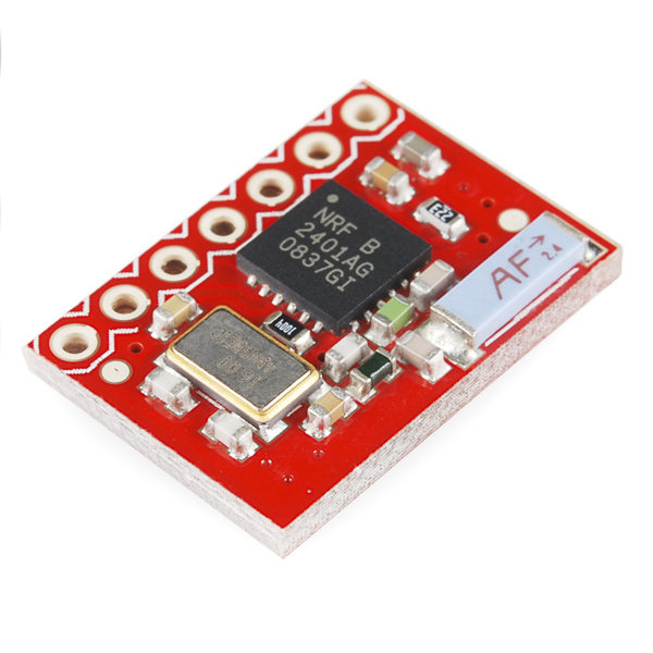
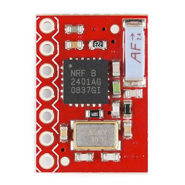
These are the nRF2401A 2.4GHz transceiver modules with built in chip antenna designed around the Nordic Semiconductor nRF2401A with high sensitivity and range. Units come with an empty 0.1" spaced footprint ready for a straight header, right angle header (recommended), or your own wires/umbilical cable.
Note: These are sold in single units. We recommend ordering two for a complete link.
- Frequency: 2.4~2.524 GHz
- Modulation type: GFSK
- Operating Voltage: 3V
- Output Power: +0dBm
- Data Rate: 1Mbps and 250Kbps
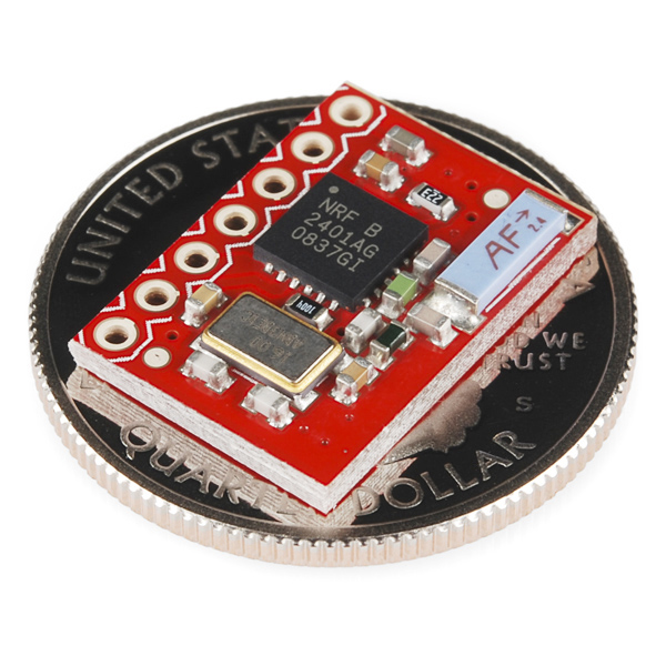
- Miniscule footprint size: 0.5x0.675" (13x17mm)
- Operating Temperature: -40 ~ +85 C
- Long range:
- 50ft. indoors
- 125ft. line of sight
- Built-in 2.45GHz ceramic antenna
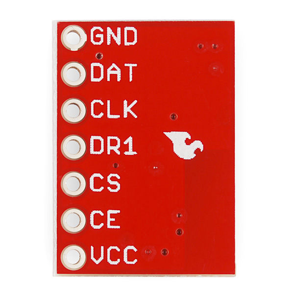
- Broken out pins:
- 3.3V VCC / GND
- CE : Chip Enable
- CS : Chip Select
- Channel 1 Interface (Data, CLK1, DR1)
- Schematic
- Eagle Files
- Datasheet (nRF2401A)
- Example Code
- Range Test
- GitHub
SparkFun Transceiver Breakout - nRF2401A (Chip Antenna) Product Help and Resources
Core Skill: Soldering
This skill defines how difficult the soldering is on a particular product. It might be a couple simple solder joints, or require special reflow tools.
Skill Level: Noob - Some basic soldering is required, but it is limited to a just a few pins, basic through-hole soldering, and couple (if any) polarized components. A basic soldering iron is all you should need.
See all skill levels
Core Skill: Programming
If a board needs code or communicates somehow, you're going to need to know how to program or interface with it. The programming skill is all about communication and code.
Skill Level: Rookie - You will need a better fundamental understand of what code is, and how it works. You will be using beginner-level software and development tools like Arduino. You will be dealing directly with code, but numerous examples and libraries are available. Sensors or shields will communicate with serial or TTL.
See all skill levels
Core Skill: Electrical Prototyping
If it requires power, you need to know how much, what all the pins do, and how to hook it up. You may need to reference datasheets, schematics, and know the ins and outs of electronics.
Skill Level: Rookie - You may be required to know a bit more about the component, such as orientation, or how to hook it up, in addition to power requirements. You will need to understand polarized components.
See all skill levels
Comments
Looking for answers to technical questions?
We welcome your comments and suggestions below. However, if you are looking for solutions to technical questions please see our Technical Assistance page.
Customer Reviews
No reviews yet.
These are awesome! Arduino code here:
http://www.arduino.cc/playground/InterfacingWithHardware/Nrf2401
I'm having trouble getting the code to work too. Currently, I'm running the transmitter code on a Arduino Mega 2560 and the receiver on a Arduino Uno. Could someone please help?
I've got the library to work in my project, excellent stuff!
Thanks for the code but it's not working. Does the code not need to call on certain pins in order for the Arduino to talk to the transceiver?
I can guarantee that code works! I made this project using those modules.
http://www.instructables.com/id/Arduino-Fart-O-Meter/
I copy paste the code and followed the pin connections.
* DR1 -> 2 (digital pin 2)
* CE -> 3
* CS -> 4
* CLK -> 5
* DAT -> 6
It's that simple!
Remember that those modules are 3.3V MAX and not 5V.
Is 3,4,5,6 Analog in or Digital?
hi again,
Can you humor me? i have hooked it up in that fashion and still nothing. i am using a atmega328 pdip-28. should i be using pins 2-6 on the chip itself or the digital pins 2-6 on this board: http://www.sparkfun.com/products/9950?
voltage isn't a problem i can see the data on the DAT pin, the clock on the transmitter but get nothing on the receiver.
I got two transceivers to work with the Arduino Pro Mini 328 using the Arduino library mentioned above (http://www.arduino.cc/playground/InterfacingWithHardware/Nrf2401).
However the transmission range of transceivers is way smaller than what the specifications indicate. I could only get it to transmit at a 4 feet distance line of sight indoors. Needless to say I'm disappointed as this becomes a really expensive wire replacement solution :(
Any thoughts on what can be done to improve the range?
Same problem here, anyone has a solution for this?
If it were me, I'd probably yank the chip antenna and try about 3cm of wire. Not sure how much improvement you ll see, but I'm willing to bet it'll be better.
Can anyone at Sparkfun provide a comment regarding the poor range reported by users in this comment stream? I want the device, but not if it only operates at 4 feet apart.
Is https://www.sparkfun.com/products/153 this same board with essentially a bigger built-in antenna?
I cant find anywhere a proper schematic on dropping the voltage for these modules. Would resistors inline with the VCC + I/O pins be the correct approach?
What happens if I accidentally connected 5V to one of these for about 30mins? Does it have some sort of protection or will it have burned out? I don't know how to check :P
There's no regulator on the board, so the 5V will be going directly to the chip. That's not good. But if it's not drawing more current than what the data sheet says, I'd give it a try and see if it'll go.
is it possible to interface this with a arduino pro mini 3v3? aka 8mhz pro mini. i had a problem interfacing a bluetooth module running 16mhz with a pro mini running 8mhz. just want to know before i buy them :)
Yes, possible. But honestly, your success will come down to the code that you write.
I still cannot connect two chips with the simple code there http://www.arduino.cc/playground/InterfacingWithHardware/Nrf2401 I'm wondering whether have wrongly connect the pins. DR1 is digital pin2. But the 3,4,5,6 is digital pin or the analog in pins?
is there a way to send the approx distance that the two units are from to each other?
I have written a short tutorial on how to connect the nRF2401A device to an Stellaris LaunchPad ARM Cortex Device! I have used quite a bit of the SparkFun.com sample code to build my tutorial, except that I translated it to ARM and added a state-machine and interrupts for better control...
Check out my blog here :
http://www.spiralwaveform.com/Blogs/Adaptive/NordicTransceiver/NordicTransceiver.htm
I will post my code to open source soon, if there are enough requests for it! Cheers to all...
Awesome! Thanks for sharing :)
Not a problem...I will post a duplicate article to my blog on CodeProject with the source download...I think I will expand the demo to become a useful library that we all can share! This way it could become more useful to the community and allow us to implement frequency hopping and dual-channel API for ARM Cortex devices. This first incarnation will be for TI Stellaris, but I will also write a port for ST Microelectronics devices. Thanks for the feedback! Mario
is it possible to replace a chip antenna with a threaded antenna connector?
Hi! Could you please post the Eagle Files. Thanks!
Sorry about that! We got them into the GitHub repo here, and will be getting them posted on the product page asap as well.
No eagle files? tear
I'm confused as to why these are still being sold. They seem to have serious range issues (I've observed 2-4 ft. range as have many others) and use the old nRF2401A. A small note mentioning that most people would probably want to go with the newer nrf24L01+ breakout would be nice! Also, why do they cost more than the nrf24L01+ when that's a better, newer chip?
Lol, I in my impatient ways ordered two of these and immediately noticed the range. Well another one bytes the dust.
If its to anyone's care, the antenna are directional and could be expected to loose connectivity while no pointing directly at the source.
I wouldn't doubt they would have range issues, as seeing how overlooked the RF design was.
Hey, a friend picked two of these up to work on a project at school... Having range issues like everyone else here. When we were approximately two feet apart, we could send single byte messages just fine (incrementing i).
By the time you drag the devices apart by about six feet, the data rate is not very good. Are we doing something wrong, or is there a issue with the board?
Using the Arduino code from sh@de.
Ok. Did a few more tests. My setup is:
1 - TX-Arduino transmits one byte, 0 to 99 with a delay of 20 milliseconds
2 - RX-Arduino counts the received packets, and displays received packet number for verification.
3 - At the end of the test, we looked at the count of the received packets. This was the 99%. OCCUPY SPARKFUN. But no, that number was the "percentage" of the packets received.
When pointing the chip antennas right at each other, we could get 100% of the packets up to about 4 feet. At 6 feet, we were starting to get 75% of the packets. If the antennas were orthogonal to each other, we would get no packets. At 8 feet we would get 30% of the packets. Also, having someone between the radios with a laptop browsing the web over wifi would drastically kill our reception rates.
Are we doing something wrong, or is there an issue with the boards?
I was wondering if anyone has used this board with the Nordic FOB WRL-08602, http://www.sparkfun.com/products/8602. I am using the Arduino Nano to try and read the data sent from the FOB, but I have not had any luck yet.
Just received a pair of these and got them working using the Arduino code at http://www.arduino.cc/playground/InterfacingWithHardware/Nrf2401
They work great, but I'm having the same issue a few other folks have commented on - the range is almost useless - only 3 to 4 feet. I checked the Arduino library to make sure the power was set correctly, and it looks like its set for maximum power out. Has anyone else been able to resolve this?
For anyone who has these - all of the pins are connected to each other on mine - there is conductivity between all of them. Is anyone else getting this or do I have a dud?
EDIT: It's OK, the pins are meant to have connectivity between them, and works just fine when ALL pins are @ 3.3V (not just VCC - I used a bunch of 10k & 15k resistors for voltage dividers). I'm getting only about 5 ft. range though too indoors, with perfect LOS. Anyone else?
I just ordered 2 of these... but am I about to regret it? The data sheet shows an 11 pin interface that gives access to the PRU pin. Above it talks about a 7 pin interface. So which is is it? If I can't access the PRU pin I probably need to cancel my order!
BTW: Got a reply over email about this... it is a 7 pin interface (datasheets are updated). Other pins can be accessed by soldering tiny wires...
The module I just got has power-up pin (23) connected to Vcc, so it is always powered on. But the datasheet shows that there should be another connection broken out for PRU. Does anyone know what to do? I need to be able to go into power-down mode.
hi sh@de i brought nRF2401A Transceiver with Chip Antenna (WRL-00152). According to the datasheet of nrf2401a power_up (pin no 23) has to be made high to enter into configurtion or active mode,but the module which i have has power_up pin left open. n since the ic package is punch QFN24 i'm not able to access that pin. so can u tell how to solve this problem.. a did u work on same module r something else.
Thank You.
Might there be mutual interference with WiFi / Bluetooth?