- Home
- Product Categories
- Weather
- SparkFun Lightning Detector - AS3935 (Qwiic)

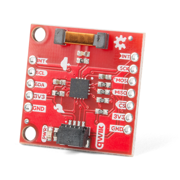
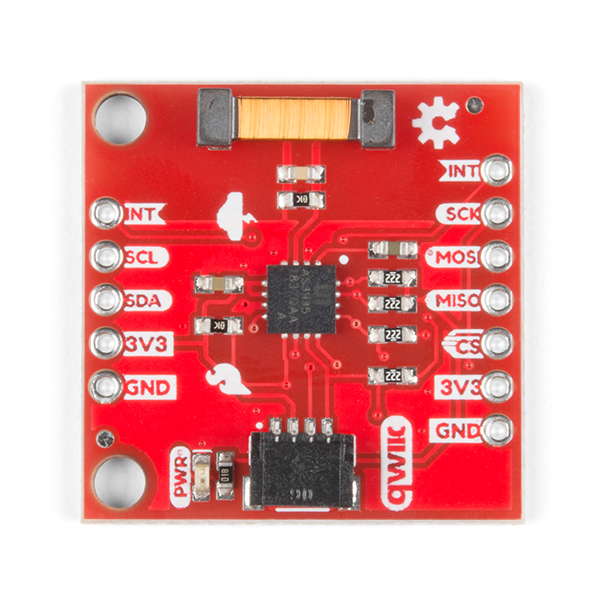
SparkFun Lightning Detector - AS3935 (Qwiic)
The SparkFun Qwiic Lightning Detector adds lightning detection to your next weather station to make sure you are aware of any potential hazardous weather heading your way. The AS3935 is capable of detecting lightning up to 40km away with an accuracy of 1km to the storm front with a sensitive antenna tuned to pick up lightning events in the 500kHz band. Utilizing our handy Qwiic system, no soldering is required to connect it to the rest of your system. However, we still have broken out 0.1"-spaced pins in case you prefer to use a breadboard.
There are a number of sources that can cause false positives but the lightning detector itself can reliably filter these out by default. If not, we've made sure to include settings you can configure using the lightning detector library to increase the chip's robustness to noise and false positives. The lightning detector library also gives you access to settings such as storm sensing sensitivity when detecting indoors vs outdoors, or the number of lightning strikes needed to trigger an interrupt.
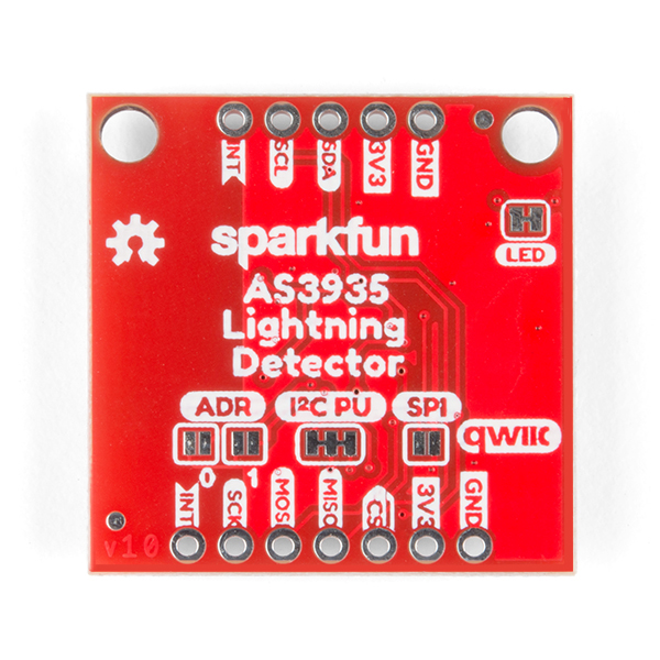
NOTE: The I2C address of the AS3935 is 0x03 and is jumper selectable to 0x00, 0x01, or 0x02 (all technically illegal). A multiplexer/Mux is required to communicate to multiple AS3935 sensors on a single bus. If you need to use more than one AS3935 sensor consider using the Qwiic Mux Breakout.
The SparkFun Qwiic connect system is an ecosystem of I2C sensors, actuators, shields and cables that make prototyping faster and less prone to error. All Qwiic-enabled boards use a common 1mm pitch, 4-pin JST connector. This reduces the amount of required PCB space, and polarized connections mean you can’t hook it up wrong.
- Lightning Sensing
- 40 km Range with accuracy of 1km in 14 steps
- Features
- Programmable Detection Levels
- Distance to storm estimation
- "Disturber" (false event) rejection algorithm
- Indoor and Outdoor Settings
- SPI and I2C Interfaces
- I2C Address: 0x03 (Optional: 0x02, 0x01, 0x00)
- Qwiic Enabled
- Operating Range
- Supply Voltage: 2.4V - 5.5V
SparkFun Lightning Detector - AS3935 (Qwiic) Product Help and Resources
SparkFun AS3935 Lightning Detector Hookup Guide (v20)
July 25, 2019
Are you worried about the looming clouds in the distance, how far away is that storm exactly? Add lightning detection with the AS3935 to your next weather station or your next bike ride!
Core Skill: Programming
If a board needs code or communicates somehow, you're going to need to know how to program or interface with it. The programming skill is all about communication and code.
Skill Level: Rookie - You will need a better fundamental understand of what code is, and how it works. You will be using beginner-level software and development tools like Arduino. You will be dealing directly with code, but numerous examples and libraries are available. Sensors or shields will communicate with serial or TTL.
See all skill levels
Core Skill: Electrical Prototyping
If it requires power, you need to know how much, what all the pins do, and how to hook it up. You may need to reference datasheets, schematics, and know the ins and outs of electronics.
Skill Level: Rookie - You may be required to know a bit more about the component, such as orientation, or how to hook it up, in addition to power requirements. You will need to understand polarized components.
See all skill levels
Comments
Looking for answers to technical questions?
We welcome your comments and suggestions below. However, if you are looking for solutions to technical questions please see our Technical Assistance page.
Customer Reviews
1 out of 5
Based on 1 ratings:
No success so far
I'm still trying to get this to work, and if I ever do I'll definitely update this review to reflect that. But I just have to wait for thunderstorms to come through for each testing/debugging session. (I'm in NJ.)
Having said that, more or less since day one I've had the board running seemingly without any errors, and with the example code always giving me a "Schmow-ZoW, Lightning Detector Ready!". I've tried both the I2C and SPI examples, during very active thunderstorms (I was even watching www.lightningmaps.org for live lightning data) and even lightning bolts almost literally over my house went completely unacknowledged. Fiddling with the different sensitivity thresholds didn't help either.
The email about this product says "Know the direction of the storm with Qwiic!"
However, all I can see talks about the distance of the storm. Does this product actually provide direction information too?
Unfortunately it does not tell you the direction of the storm, only the distance.
Does this board come with the appropriate antenna tuning cap value to use in setup, like the one from PlayingWithFusion does?
And beware; these things are quite sensitive to noise from things like switching power supplies and neopixels. My AS3935 neopixel lightning detector required a linear power supply and some distance from the neopixels to work.
Indeed it does. The RCI circuit is specified by the manufacturer of the AS3935 IC and we've had very good reliability with the setup.
There is a CircuitPython library now available for the Qwiic AS3935 Lightning Detector and the Raspberry Pi. The source code, examples, installation information and documentation are available on GitHub.
https://github.com/fourstix/Sparkfun_CircuitPython_QwiicAS3935
So, I connected this to a Sparkfun Thing Plus via a qwiic cable, compiled the basic example code included with the library, and it never successfully starts up. Any ideas what may be happening or ideas on what I can check?
For technical support, please head over to our forums and post a new topic. We will do what we can to assist you with this issue.
Well the LED works. Connected it to a Raspberry PI 0w and ran sudo i2cdetect -y 1 and the other 4 sensors I had connected showed up 0x44,0x45,0x60,and 0x77 but no 0x03. tried it again without the other sensors and nothing.
Changed Pull Up resistors to 10k and tried it on another Raspberry Pi 0w... Seems to be working now.
Looks like the Qwiic connector is only 4 wires, but this requires an interrupt. So you still have to solder the interrupt pin?
Yes, unfortunately it does require an additional pin to be connected. I have used these IC hooks for just this purpose: https://www.sparkfun.com/products/9741.
If you look at the hookup guide under "Hardware Assembly" you can see a picture of how I used the IC hook to avoid having to solder anything.
I never got any of my 3 purchased PlayingWithFusion sensors to work which uses the same chipset. I got false readings all the time, and at one time when a thunderstorm was right ontop of me, it didnt detect anything. And i used a linear powersupply, however my arduino which i had it connected to, did not!
The datasheet tells it has only 40% chance of detecting lightning if i remember correctly. Regarding the direction, i wanted to have 3 sensors spread out over the town i live in, which reported the signal strength and timestamp to a SQL server of mine, that way it would be possible to triangulatea aprox where it struck down :) But since i never got my sensor to work, i had to give up on this. I really like the site lightningsmaps.org, this is a community driven project, and somewhere on their site, there are instructions how to build a sensor of your own and contribute.
What is the difference between this one and the SPX-15057? Is it just that going forward this is the commercial version that will be available?
That's correct. SparkX products will occasionally migrate to the SparkFun catalog and if the SparkX version isn't already retired, it will retire shortly.
Sorry ... this is not a reply ... it is a new comment ... I couldn't figure out how to enter a new comment. Anyway: I have the Lighting Detector operating over I2C with an Arduino. I've noticed that the setting need to be tuned to prevent a lot of false alarms. Can the S/W be updated to poll the device to determine its current settings? While you're at it, can you make clear the min & max value for each setting? Thank you. Paul
I'm going to give an extended answer in case there are others with this question, so bear with me. To begin there is a way to test the resonance frequency of the on board antenna, which of course is vital to the function of the product because it "resonates" with lightning (or environmental noise - more on that later). In testing this design before release, I found the accuracy of the antenna to be ~2 percent from an ideal 500kHz resonance frequency. The datasheet specifies that it should be within 3.5 percent for accurate lightning detection. With that said, last week I extended the example code included with the library (Version 1.1.1) to include a sketch that walks you through how to take advantage the internal capacitors in the AS3935 to tune that frequency. This will require that you have some method of reading square wave up to 30kHz (check the comments in the example code why this isn't 500), something like a logic analyzer or oscilloscope.
Now a note on noise. These things are really sensitive, things like your phone screen, monitor, a refrigerator turning on, soldering iron, to name a few, can trigger false positives.The basic example sketch shows you how increase the robustness of the antenna with a function to increase the noise threshold (value 1-7, default is 1). The example code also defaults to an "indoor" setting, if you're indoors, make sure that is still the case. There is also another function to help increase the robustness against "disturbers" a.k.a. false events (watchdogThreshold() which takes a value from 1-10, default is 1). Hope that pushes you in the right direction. Check the library for more functions that may help you, though if you need more than the two I just listed, you may have to remove noisy items in your environment.
I've lashed the AS3935 'Ding Dent' breakout to an ESP32, using I2C and ESP-IDF, and have yet to see the I2C interface stop working. How long does it take in your experience for the I2C interface to stop working? I'm wondering if there's something specific to the Arduino IDE.
If the MCU in use has a pin that can be used as a counter input and interrupt, then you can automatically calibrate the antenna at start-up, which is what I do with the ESP32.
Out here in the SF Bay Area, we don't see a lot of electrical storms, but I appear to have accurately detected a storm passing-over near this morning; interestingly, there was a cluster of disturbers immediately before the lighting - which makes me think disturbers can also be natural electrical activity that isn't a ground-strike:
So - I'm most interested in what the I2C issue is, is it a known erratum for the AS3935?
Cheers, Dana
Thank you, Elias, that is a good fraction of the information I was looking for. I believe there is also a "spikeRejection" function ... could you state the allowed range of values for this as well? Finally, could you provide examples using the "readRegister" function to determine what settings the Detector has been set to? Thanks again. Paul
The text above each function explains what it does, the possible values that can be taken, as well as the default values that the lightning detector is set with. I would encourage you to read about spike rejection in the data sheet; download the .pdf from the documents tab above and search for Spike Rejection, it's kind of vague but perhaps you could pull more from it.
To use readRegister(), give the function the register (e.g. 0x01 for noise level), followed by the amount of bytes which in 99 percent of cases is one: readRegister(0x01, 1). This will return the value within the register which you can then print out and compare to the default values of the register found in the datasheet.
These types of questions are made for the forums so I'll push you there for any future questions. https://forum.sparkfun.com/index.php