- Home
- Product Categories
- SparkX
- SparkFun BlackBoard C

SparkFun BlackBoard C
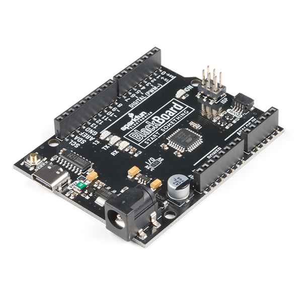
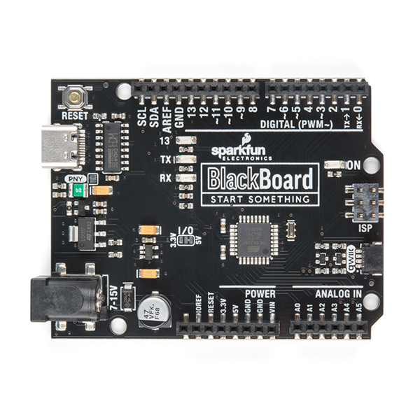
The BlackBoard from SparkFun is everything you need in an Arduino Uno with many extra perks. BlackBoard has all of the hardware peripherals you know and love: 14 Digital I/O pins with 6 PWM pins, 4 Analog Inputs, UART, and SPI with a handful of external interrupt pins. BlackBoard even has an SMD ISP header to connect SPI pins to shields.
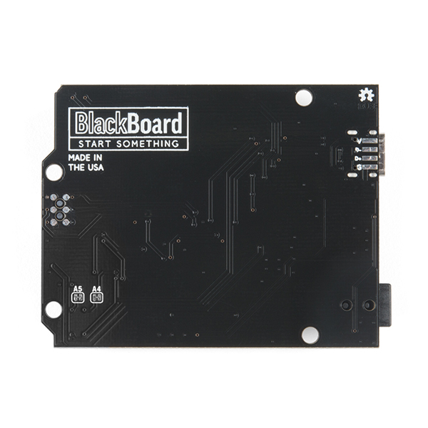
We've applied every lesson we've learned about making a better Uno and created the BlackBoard. The USB to serial is now done with a reversible USB C connector with through hole anchoring and the ubiquitous CH340C requiring fewer driver installs. The power portion of the BlackBoard has been reworked: we upgraded the 3.3V regulator to provide up to 600mA, with full thermal and reverse circuit protection, and added extra decoupling capacitance to increase the sensitivity of the ADC readings. We've decreased the brightness of the power LED, pin 13 LED, and the TX/RX LEDs from blinding to just perfect. We've added 3.3V voltage translation and a Qwiic connector to the edge of the board to allow for quick and seamless connection to our ever-growing line of I2C based Qwiic products. We've added solder pads to the bottom of the board for D+/D- so you can embed your BlackBoard into a project and run an external USB connection. We've increased the height of the reset button. This doesn't sound like much, but everyone who's touched it loves the improvement. And finally, we've increased the PTC from 500mA to 2A so that you can capture the full power of USB C.
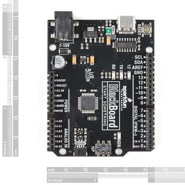
For more advanced users we've added an I/O jumper. Cut the trace to 5V and solder a jumper to the 3.3V side and the board will run at 3.3V. This is extremely handy if you have a shield or 3.3V sensitive devices, such as an SPI interface, that needs protecting.
The SparkFun BlackBoard comes fully tested with the Optiboot bootloader and can be easily programmed with the 'Arduino/Genuino Uno' option from within Arduino. You can power the BlackBoard over USB or through the barrel jack. The on-board power regulator can handle anything from 7 to 15VDC. The barrel jack can support up to 2 amps while the USB connection is limited to 0.5A. Check out the related items below for a compatible wall-wart power supply.
Not sure which Arduino or Arduino-compatible board is right for you? Check out our Arduino Buying Guide!
A4/A5 Pins: We recommend you don't use A4/A5 for analog to digital conversion. These pins have external 2.2k pull up resistors and will affect readings if you use them as analog to digital conversion pins. A0 through A3 still work fine as ADC pins. However, there are two jumpers on the rear of the board that can be cut to disconnect the 2.2k pull ups if you need the extra A4/A5 ADC pins.
- ATmega328P microcontroller with Optiboot (UNO) Bootloader
- CH340C USB to Serial IC
- Reinforced and reversible USB C connector
- Built-in Qwiic connection
- Input voltage: 7-15V
- 0-5V outputs with 3.3V compatible inputs
- 14 Digital I/O Pins (6 PWM outputs)
- 6 Analog Inputs
- ISP Header
- 32k Flash Memory
- 16MHz Clock Speed
- Flat bottom, all SMD construction
- Schematic
- Eagle Files
- Drivers: The CH340C uses CDC drivers built in to most modern OS including Windows 7, 8, 10, Linux Mint, OSX Yosemite, El Capitan, and Sierra which means you shouldn't need to install any extra software. However, there are a wide range of operating systems out there, so, if you run into driver problems, you can get drivers here.
- Arduino IDE Download
- Please visit the BlackBoard repo for the latest design files
SparkFun BlackBoard C Product Help and Resources
How to Install CH340 Drivers
August 6, 2019
How to install CH340 drivers (if you need them) on Windows, Mac OS X, and Linux.
Comments
Looking for answers to technical questions?
We welcome your comments and suggestions below. However, if you are looking for solutions to technical questions please see our Technical Assistance page.
Customer Reviews
4.5 out of 5
Based on 2 ratings:
2 of 2 found this helpful:
My new go-to for the Uno line
I now own the new version (rev C) and the previous one, and the more I use it the more I appreciate its simplicity and well thought-out design. It is clear Sparkfun is all-in on the Quiic system (and for a good reason). The way the provide support on the Blackboard is excellent; the Qwiic connector contains the level translator for the +3.3V Qwiic system, but the SDA/SCL lines still maintain +5V support. The USB-C is a plus (the more I use it the more I love the standard).
This is no ARM board, but for the Uno line this is my new go-to for quick development.
1 of 1 found this helpful:
This thing is fantastic! FIVE STARS, NOT FOUR!!
Other than agreeing with the other reviewer in saying that this is my new go-to board if I need an Uno platform. It fixes literally every single qualm I had with the original vanilla design. I am slightly confused by what seems to be an extra pair of jumper pads below the USB-C connector labeled "PNY". Or is that just referring to something else, and they're just for testing the board in the factory? Other than that, I feel like I know this thing inside and out! EDIT: I just realized I forgot to change the star rating, I meant to make it a 5/5. Well done y'all.
Thank you! The PNY jumper is my tongue in cheek joke. It's the 'penny' jumper. If you close that jumper, you short across the PTC fuse, effectively putting a penny in the fuse holder. Sorry, the schematic was old. I've updated it. Thanks for pointing that out!
Took me a while to figure out why my Vernier sensors (using Vernier shield) weren't auto id-ing with the Blackboard. Turns out the auto id uses A4/A5 and those pins have 2.2 k pull up resistors, and this throws off the id voltages that the VernierLib uses to id a sensor. I'll need to cut the jumpers as discussed in the description.
This will help other users. Up voting. Thanks for reporting!
[Note: I was instructed to move my comment from the redboard qwiic to this product] If it wouldn't be too much trouble, could you replace the voltage selection solder jumper with either a small switch or a header that accepts a jumper in one of two positions (in the next revision)? Solder jumpers make it too easy to create unintended circuits once they have been switched more than once due to residual solder.
I have thought about this for years and it worried me: I would always be afraid of bumping the slide switch and making the system go to the wrong voltage, potentially frying a bunch of stuff. Is there a good solution in the middle (easier than solder jumpers but more fault tolerant than a slide switch)?
Currently, my only other idea is a jumper cap on a 3pin 90degree header (bigger but easier)
0) If you are worried about bumping the slide switch, have you considered the possibility of bumping the jumper with something conductive like a screwdriver so as to briefly connect the 5V pad?
1) Bumping a slide switch is one of the harder ways to send 5V to 3.3V electronics, given that USB/input power is 5V+ and those pins are always exposed for accidental wiring
2) The bump would have to be exactly in the right spot and direction to have a chance at toggling the switch
3) You could tell people to put a bit of clear tape over it to rule out bumping entirely
4)It wouldn't affect the QWIIC connector (which must always be 3.3V)
5) People who install a shield that could potentially be destroyed would automatically block the slide-switch from view
6) This form factor is most useful for rapid prototyping of ideas, not building a mission-critical product. The speed afforded by a slide switch is therefore justified.
7) Most non-I2C parts are 5V or 5V tolerant anyways, at-least in my experience
I've got some nits with your points but overall you make a convincing argument (thanks!). I agree with you. I'll put a switch on the next version.
Posted
<3
I got the previous version of the Blackboard and the newest (rev C). It is a really good dev board. The USB-C is a plus. The Qwiic support if very well thought off; the Qwiic connector contains the level translator for the +3.3V Qwiic system, but the SDA/SCL lines still maintain +5V support. For the Uno line, this is my new go-to.