- Home
- Product Categories
- Development Tools
- 18 Pin PIC Development Board

18 Pin PIC Development Board
Replacement: None. It's time for this product to step aside and make room in the catalog for even more cool stuff. This page is for reference only.
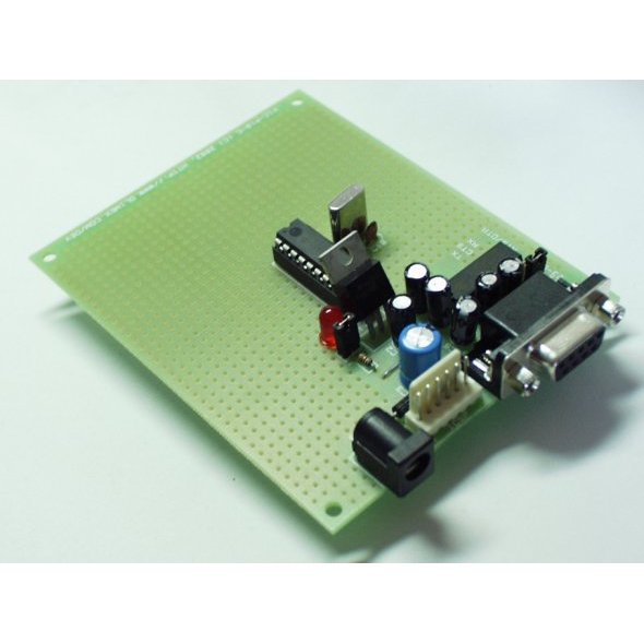
Prototype board for 18 pin PIC microcontrollers with power supply circuit, 20MHz crystal oscillator circuit, RS232 port, and ICSP/ICD programming port.
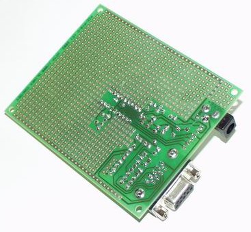
- FR-4, 1.5 mm (0.062"), green solder mask, white silkscreen component print
- Four mounting holes - diameter 0.13" (3.3 mm)
- ICSP/ICD connector for programming with PIC-PG1, PIC-PG2C, and debugging with PIC-ICD1 (for the PICs with ICD support) or PIC-ICD2
- Power barrel jack
- Voltage regulator +5V, 7805 and filtering capacitors
- LED to RB3 through jumper
- Crystal oscillator circuit 20Mhz
- DIL18 microcontroller socket
- RS232 DB9 female connector
- RS232 MAX232 interface circuit with Tx, Rx, CTS, DTR/RTS signals
- Extension slot on every uC pin
- Grid 100 mils
- GND bus
- Vcc bus
Board does not come with PIC installed. Please see a list of related ICs below.
- 3.9x3.15" (100x80mm)
Comments
Looking for answers to technical questions?
We welcome your comments and suggestions below. However, if you are looking for solutions to technical questions please see our Technical Assistance page.
Customer Reviews
No reviews yet.
Just to clarify: use this board with 18-pin PIC16's, not PIC18. The latter will end up connecting the USART RX pin to the ICD PGM pin TX to the LED, while leaving its PGM pin floating. Jumpering pins 10 and 11 for PIC18 works to obtain ICD connectivity, but there is no RS-232E functionality without cutting a few traces and rerouting the LED.