- Home
- Product Categories
- Other LEDs
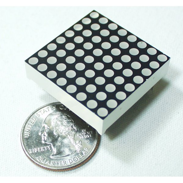
- LED Matrix - Dual Color - Small

LED Matrix - Dual Color - Small
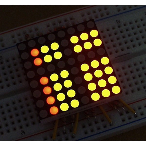
LED Matrix with dual-color LEDs. This small matrix has both bright-red and bright-green LEDs built into one common cathode housing.
Unit comes with a black finish and a opaque LED lenses.
The picture does not quite do the matrix justice. The Red and Green LEDs are quite clear, and turning both on creates a nice yellow color.
- 0.275x1.25x1.25"
LED Matrix - Dual Color - Small Product Help and Resources
Core Skill: Electrical Prototyping
If it requires power, you need to know how much, what all the pins do, and how to hook it up. You may need to reference datasheets, schematics, and know the ins and outs of electronics.
Skill Level: Competent - You will be required to reference a datasheet or schematic to know how to use a component. Your knowledge of a datasheet will only require basic features like power requirements, pinouts, or communications type. Also, you may need a power supply that?s greater than 12V or more than 1A worth of current.
See all skill levels
Comments
Looking for answers to technical questions?
We welcome your comments and suggestions below. However, if you are looking for solutions to technical questions please see our Technical Assistance page.
Customer Reviews
No reviews yet.
If anyone is still interested in knowing the pin distribution and layout, check this link: https://docs.google.com/open?id=0B9pe6NMkbFJfSGhpRnVUcXZtVW8 I made a PDF with basic information such as: Pin numeration, LED layout, Vdrop, Resistance value, I(LEDs). I hope it will be useful for you.
Thanks for the good information.
We have been receiving reports that the data sheet shows the red and green leds in reverse order to how they actually are. So if it happens to you, you are not the only one :-)
I'm designing a backpack kit for these that is daisy chain-able to any length. See my blog here http://www.billporter.info/?p=374 .
My goal is to keep costs very low, and so far, so good. I'm looking for some evaluators if anyone in interested, leave a comment on my site.
I've made a Eagle library for the medium one of these so I've added this one to the library too.
You can find it here: http://insidegadgets.wordpress.com/eagle-libraries/
Please do a 1:1 print out to confirm, I followed the data sheet so let me know if the pins are actually for the correct red/green lights.
I was just looking at these about an hour ago the price went up by $2. :S.
According to the datasheet as well as personal experience, the rows are not at standard breaboard/2.54mm spacing. You may have to bend the pins (a lot) or get/make a BoB. (The rows are 24.00mm apart; the closest breadboard-compatible spacings would be 22.86mm or 25.40mm)
:(
How did you get it in, Sparkfun? Did you bend the pins?
Looking at the other pictures, it looks like soldered female headers...
As Sparkfun is out of stock, if you need to purchase these you can get them for ~1$ each from sure electronics, FYI just bought 30 for 9.99/10.
Check that. I just tried the ones I got, they're common Anode, not cathode like these.
"LED Matrix - Dual Color - Small"
So you mean 4 color: red, green, yellow, and off. And that doesn't include what you could do with PWM...
No, they mean Dual Color, as in a Red LED, and a Green LED. Not tri color, red, green, blue, not quad, two LEDs. Does your car have 3 headlights? On, Off, and High beam?
Arduino Example/Library?
Found a typo in the datasheet in the notes section: "Dot Matrix is sensitive to satics, be sure your equipments are anti-static when you use our Dot Matrixs." Isn't it sad that major manufacturers make more errors than SFE?
I purchased one of these and am having a hard time figuring out how to hook it up using the data sheet. The pins on the underside run along the top and the bottom yet the data sheet only indicates the numbers running along the top and left side. And what is the orientation of this thing?
Could I use this with a 74HC4514 for an Arduino-controlled Snake game?
is there an eagle part for this?
any chances on a rear/back view???
Im new to electronics and Arduino. Where can I find some cool/easy projects to do with the dual-color small LED matrix?
it is very simple to use one of these with arduino, I have written a short tutorial, located inside http://bit.ly/am6iAx
Can anyone tell me if there is a serial interface backpack for these small LED arrays?
The backpack for the large LED array looks fine (COM-00759), but are they available for these small ones? Thanks
How much power is required to run these things? More precisely, how much is required for 24 of these to run at once?
This is a cool part but guys, we really need the Eagle Lib for that! Can you see these lot of comments requesting for it???
Also i agree that previous batch from Kingbright was farly more bright and with more quality than this from YS... I strongly suggest to go back to Kingbright series, even if it is more expensive than the YS model.
I found Pin 1 using this technique. The chip has 12 pins on each side and pins run parallel with the rows.
I setup a test circuit with a 5V supply and 220 Ohm resistor.
I oriented the chip so one row of pins runs along the bottom. Counting left to right, attach 5V and resistor to what could be the actual Pin 1 on the chip (call it "candidate" pin 1) and GND to "candidate" pin 3. This should turn on the red LED (see Note below) at row 5, col 5. If this is the case, then 5V is connected to the actual Pin 1 on the chip and GND is connected to actual Pin 3.
If nothing lights then swap the connections so that GND is connected to "candidate" pin 1 and 5V is connected to "candidate" pin 3. This should turn on the red LED (see Note below) at row 5 col 5 based on the current orientation of the chip. If this is the case, then GND is connected to the actual Pin 13 on the chip and 5V is connected to Pin 15. This also means that you are actually lighting Row 4 Col 4 because the chip is upside down based on the schematic.
Once I identified the pins, I wrote on the side to mark them.
Note: As best as I can tell, the schematic on the data sheet is not correct. In my experience, red and green were reversed.
I can't seem to find out how this matrix works. Is there atleast a small tutorial for it? Like for how to use the pins?
I am uncertain if this is product is still a mystery due to the lack of pinout information present in the datasheet. Even after searching, I couldn't find much information on this.
I spent some time tinkering with it and I think I've figured out the pinout. I am uncertain if the "YS" stamp is present on the same side of all of the modules (or if they are stamped randomly).
On mine, pin one was present on the left-most pin when looking at the side with "YS" stamp (see picture):
http://retfie.com/front.jpg
I also took a picture of the underside to locate pin one based upon the PCB.
When looking at the PCB text (underneath the epoxy coating), pin one is located bottom left (see picture):
http://retfie.com/bottom.jpg
If someone could confirm this is the case for all modules, it might help others, I think.
-Omar
Oops. Made a typo:
"When looking at the PCB text (underneath the epoxy coating), pin one is located bottom left"
This should read "bottom right".
Much better when the batch was from Kingbright. This seems to be less in quality.
Note that the latest batch (5/2009) of these displays, marked only with a "YS" stamp, are significantly dimmer than the previous batch. The previous batch had a part number that resembled the data sheet. Do not expect to be able to mix parts from these different batches! The pinouts and footprint is the same, but the brightness will not match.
Is there a tutorial for getting these working (or something close).
I also agree with John. Difficult to figure out which pin is pin one. Don't seem to be any markings on the unit to indicate 'top' or 'pin 1' or other useful type designation.
Unlike the large RGB matrix, this one doesn't have markings/notches on the sides of the package. What is the best way to determine the pin numbers on the 8x8 dual color (small) matrix?
If you look at the bottom, there are pin numberes in the epoxy. rule of them, if you hold the display so the black model number on the side is facing down, then pin 1 will be bottom left, but hold it upside down and look for yourself (I'm going off the Sure Electronics LE-MM103 displays)
just like these guys can some one save me the frustration and help a brother out with some pinouts.. or at least a simple explanation ? ..
thanks
--dick
Wow! Sorry about that. Datasheet is now updated to a much more readable, friendly PDF.
Does anybody know where I can find a pin diagram for this? I've found a couple PDFs online, but none that I can read without getting a language pack, that my computer seems to find incompatible.
do you have an eagle library for this LED Matrix