- Home
- Product Categories
- Other LEDs
- LED Matrix - Dual Color - Medium

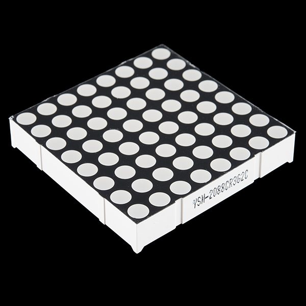
LED Matrix - Dual Color - Medium
LED Matrix with Bright-Red and Bright-Green LEDs. This medium matrix has 64 Red/Green LEDs built into one common cathode housing.
Unit comes with a black finish and a opaque LED lenses.
- 0.33 x 2 x 2"
LED Matrix - Dual Color - Medium Product Help and Resources
Core Skill: Electrical Prototyping
If it requires power, you need to know how much, what all the pins do, and how to hook it up. You may need to reference datasheets, schematics, and know the ins and outs of electronics.
Skill Level: Competent - You will be required to reference a datasheet or schematic to know how to use a component. Your knowledge of a datasheet will only require basic features like power requirements, pinouts, or communications type. Also, you may need a power supply that?s greater than 12V or more than 1A worth of current.
See all skill levels
Comments
Looking for answers to technical questions?
We welcome your comments and suggestions below. However, if you are looking for solutions to technical questions please see our Technical Assistance page.
Customer Reviews
No reviews yet.
I also had trouble figuring out the connections, but I managed it in the end.
Here is a post on my blog with my findings:
http://www.glowseed.com/mindmash/?p=239
or you can skip directly to the PDF pin specification I wrote:
http://www.glowseed.com/mindmash/wp-content/uploads/2009/05/pins-led-matrix-dual-color-medium.pdf
The link to your PDF is dead now. I've written a blog post that shows how to get 256 colors out of it, while enjoying the graphics library from adafruit and sending your own multicolor bitmaps easily (ISR routine with binary code modulation for PWM): http://marc.merlins.org/perso/arduino/post_2015-01-06_Driver-for-direct-driving-single-to-3-color-LED-Matrices-with-software-PWM.html and https://github.com/marcmerlin/LED-Matrix
Hmm, I think your pinout version is wrong, this is the results I got. It shall be vice versa! Pinout
This was very helpful - thank you!
Wasn't sure if I could drive the green LED's off a 3.3V supply since that was the forward voltage listed on the datasheet. I measured the i-v characteristics of the red/green LED's, and the forward voltage is really actually around 2.2V, not 3.3V! Hope it helps someone else:
http://i.imgur.com/8OkBB.png
This is exactly what I was going to ask. I figured I'd just drive the green with the 3.3v off the Arduino, but now that I see the forward voltage is 2.2V rather than 3.3V, I won't do that. Thanks!
I've written a blog post that shows how to get 256 colors out of it, while enjoying the graphics library from adafruit and sending your own multicolor bitmaps easily (ISR routine with binary code modulation for PWM): http://marc.merlins.org/perso/arduino/post_2015-01-06_Driver-for-direct-driving-single-to-3-color-LED-Matrices-with-software-PWM.html and https://github.com/marcmerlin/LED-Matrix
Try the MAX6961, 2, 3, or 4 devices. They should work with this.
Hi, I got 4 of these before realising that driving these chips is harder than single color arrays (easily supported by MAX7219s).
Do you think it is easier to use an HT16K33 to drive these arrays?
Evidently, the datasheet title says 8mm pitch, but mechanical dimensions specify 6.35mm pitch. Would anyone be kind enough to identify which of the two is the errata?
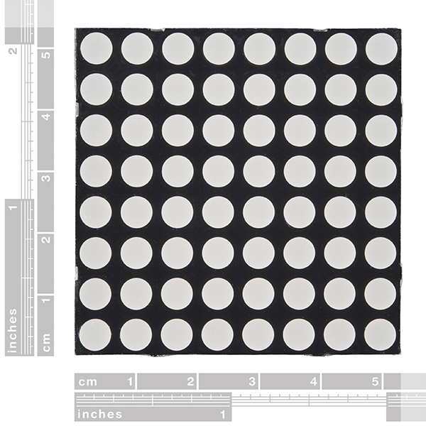
I just measured the LED pitch with a micrometer. It is 44.45 mm from LED 1,1 center to LED 8,1 center, or 6.35 mm pitch.
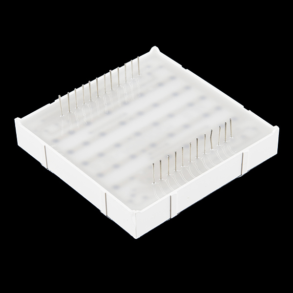
The pins, however, are 100 mil pitch, just to be clear.
this may help figuring out the pins the black dots are ground http://i.imgur.com/Ivd5t.jpg
Has anyone found a breadboard this fits onto?
Try two breadboards that are connected.
This should fit just about any breadboard? The pins are standard 0.1" (2.54mm) spacing next to eachother, and the two rows are only 1.5" (38.10mm) apart.
Mine didn't have any writing that I could've used to find the pinout, so I experimented and this was my pinout.
http://i56.tinypic.com/2ppwz1d.jpg
Hold the matrix like in the picture (with the two protruding "notches" on the top and on the left)
How would i pick between the red and green LED's? Different voltages supplied? Different pins for each LED color?
Thanks!
No, there are no logic circuits in this matrix (i.e. you can't use different voltages to make the colors change).
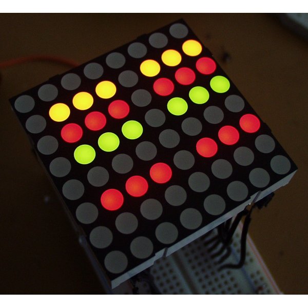
The way it works is you have 24 pins. 8 pins are for negative lines for each row of leds, and then you have 8 pins that are for the positive lines for each column of the red leds, and then you have 8 positive pins that are for the yellow leds.
To light them, you have to set a negative charge for which pin row you want, and a positive charge to the pin column for which color you want (you would charge red and yellow for that one led to get green).
Womble's first post shows the correct pin order for this part btw.
Also if you still don't quite understand, check out fritzing page on a 3x3 led matrix to get a gist of how it works:
http://fritzing.org/projects/multiplexing-a-3x3-led-array-with-an-arduino/
Thank you! Here is my resultant project:
http://www.youtube.com/watch?v=ELtsEPXV2xE
mHo2: wanted to watch your video, but your link goes nowhere...
My apologies! Has been edited.
Cooool!
sry dbl post. Admin please remove.
I bought a similar one of these from another place, though mine was 60mm instead of 50mm and pin 1 was located somewhere else.
I made a Eagle library for this one: http://insidegadgets.wordpress.com/eagle-libraries/
Let me know if it matches 1:1
Check out the Puzzlemation project page linked in the first comment. Near the bottom there's a PDF file with a schematic showing how to connect it up.
Ah...I think I saw how to identify and the pins for the row and the pins for the column by the marks along the edges of the LED matrix.
newbie question:
This 8x8 LED dot-matrix has two rows of pins. Reading the schematic, I am still confused which row of pins is for the column and which row of pins is for the row.
Looks like the column is common anode and the row is common cathode. That means to turn on an point (LED) in the matrix I apply the power (the V+) to a common anode column and GND to the common cathode row?
Thanks!
does anybody know where to get a eagle library for this component? or a pcb design to control one or two matrixes like this one with MAX7219GNC??
Hi,
I looked at the datasheet. So is that common anode for the row and common cathode for column? Thanks.
I'm waiting for a LED matrix from one month ago, but they are always out of stock. Are you going to bring some more, or must I ask some other electronic distributor?
These work great - I recently used them for this project:
http://www.puzzlemation.com/
Very easy to interface to a PIC24F by using a ULN2803 to help sink the current.
This is amazing! I'm curious, how did you make shapes with the LEDs? Did you have them flash at a rate that wouldn't be detectable by the human eye? I have the common anode version of this part at home and I'm trying to figure out how to make the shape of an arrow, but I'm having trouble. Lets say I'm trying to light up dots ([row] [column] ) [1][1], [8][1] and [4][2]. It will light up [1][1], [4][1], [8][1], [1][2], [4][2] and [8][2]. Do you understand what I mean?
To summarize my comment, how do you control each LED individually?
You'll need to build a circuit that applies power and ground ONLY to the crosspoint of the LED you want to light up. Do this fast enough (scan through all the combinations) and you're there. There are lots of useful links in these comments. Also, take a look at our Serial matrix schematic, and this driver chip may be useful.
I'm curious, what did you use to control the matrices? Was it just shift registers? Where did you get yours?
I used a combination of a PIC24F and a ULN2803 to sink the cathode current. All of the lines were driven by the PIC24F. More details are on the Puzzlemation web site.