- Home
- Product Categories
- Monochrome
- Basic 16x2 Character LCD - Red on Black 5V

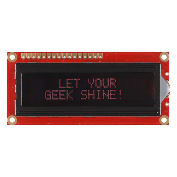
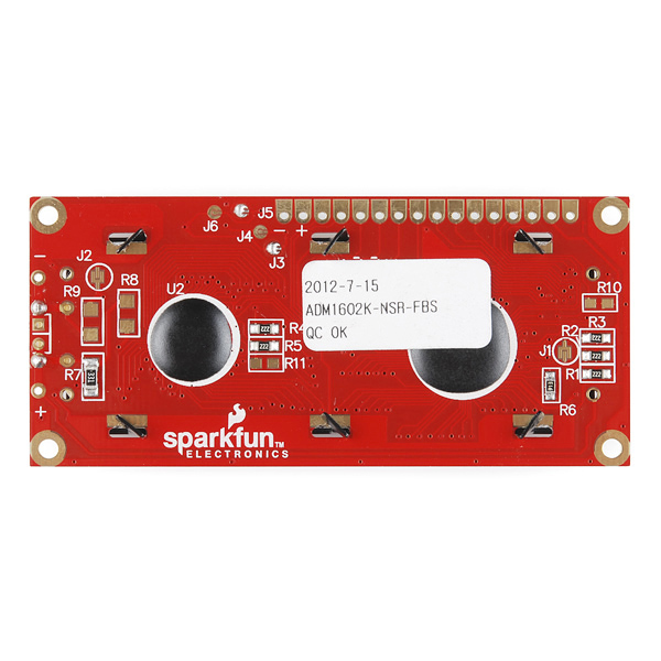
Basic 16x2 Character LCD - Red on Black 5V
This is a basic 16 character by 2 line display with a Black background and a Red backlight. Utilizes the extremely common HD44780 parallel interface chipset (datasheet). Interface code is freely available. You will need ~11 general I/O pins to interface to this LCD screen. Includes red LED backlight. These modules are the thin type.
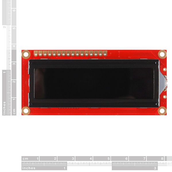
****3.15" x 1.425" x 0.300"
Basic 16x2 Character LCD - Red on Black 5V Product Help and Resources
Basic Character LCD Hookup Guide
May 28, 2019
Liquid crystal displays (LCDs) are a great way to output a string of words or sensor data to a display for visual feedback. In this tutorial, we'll learn about LCDs, how to print a string of words to a 16x2 basic character LCD and create custom characters.
Core Skill: Soldering
This skill defines how difficult the soldering is on a particular product. It might be a couple simple solder joints, or require special reflow tools.
Skill Level: Noob - Some basic soldering is required, but it is limited to a just a few pins, basic through-hole soldering, and couple (if any) polarized components. A basic soldering iron is all you should need.
See all skill levels
Core Skill: Programming
If a board needs code or communicates somehow, you're going to need to know how to program or interface with it. The programming skill is all about communication and code.
Skill Level: Rookie - You will need a better fundamental understand of what code is, and how it works. You will be using beginner-level software and development tools like Arduino. You will be dealing directly with code, but numerous examples and libraries are available. Sensors or shields will communicate with serial or TTL.
See all skill levels
Core Skill: Electrical Prototyping
If it requires power, you need to know how much, what all the pins do, and how to hook it up. You may need to reference datasheets, schematics, and know the ins and outs of electronics.
Skill Level: Competent - You will be required to reference a datasheet or schematic to know how to use a component. Your knowledge of a datasheet will only require basic features like power requirements, pinouts, or communications type. Also, you may need a power supply that?s greater than 12V or more than 1A worth of current.
See all skill levels
Comments
Looking for answers to technical questions?
We welcome your comments and suggestions below. However, if you are looking for solutions to technical questions please see our Technical Assistance page.
Customer Reviews
No reviews yet.
I cant figure out whats going on with my LCD. I used the Arduino Liquid Crystal Hello World example double and triple checked the schematic, and currently, all the text is scrambled. It appears to be working otherwise though. Just cant figure out why the text is scrambled.
Hello, World! -> "¢£¢¢ö, █öø¢¢!" 0-3 are ok, then 4 -> < 5 -> = 6 -> > 7 -> ? 8 -> < 9 -> = 9
How much current does the backlight draw? Thanks!
This would make a better display for this
for interfacing this LCD with 16bit PIC microcontroller here is an example code
http://ibrahimlabs.blogspot.com/2013/06/how-to-interface-lcd-in-8-bit-with_23.html
Oh no! Where did "All your base are belong to us" go?
For the backlight voltage being specified at 4.2V or 4.6V, depending on what part of the data sheet you look at, I used a small signal diode (1N914) in series with a 10 ohm resistor to drop my 5 V supply voltage a little. My display is drawing 17mA while showing text. Actually, that includes an ATtiny84 and pressure sensor, but probably most of the current is going to the LCD. One oddball glitch - I can't get the cursor to turn off. The command is 0b00001DCB where C is 0 for cursor off and B is 0 for cursor blink off. I finally had to change C to 1 (cursor ON) to get the blinking to stop. I still have a static underscore cursor, but that's not as bad has having the whole digit blinking on and off. Very strange. Nick
I made a tutorial (in portuguese) about how to use, create custom characters and design menus for the LCD display. Take a look: http://engenheirando.com/arduino/displaylcd/
Question: I purchased a 5V LCD but have since decided I'd really like my next project running at 3.3V. Is there an easy-ish way to convert this to run on a 3.3V circuit? I'm assuming the SMD resistors on the back are chosen for both logic level and LED forward voltage for 5V. I can always buy another board or a step-up break-out, but thought it was worth asking the community if changing the voltage on these boards is easy?
I'm sure you've gone a different way by now, but i'm putting this here for other people looking for an answer.
The deal with HD44780/compatible LCDs is that the contrast voltage (sometimes referred to as the "bias" or "Vee" in datasheets) should be 4-5.5V BELOW Vcc/Vdd. That's why at 5v the screen is basically blank for most of the range of your pot and then the last 1/5 or so seems like a hair trigger. Unfortunately at 3.3V this means your visible range will be between NEGATIVE 0.7V and NEGATIVE 2V. Bummer!
What you need is an inverting charge pump to supply a negative voltage from your 3.3v.
I'm not sure about sparkfun's LCDs, but most HD44780 LCD modules have an unpopulated SOIC-8 footprint and spots for a couple capacitors. You would need to populate the SOIC footprint with a 7660 charge pump (available from Maxim or Intersil) and the caps with 10uF. I don't see that footprint in the picture but i guess it's possible it might be under the sticker. If not you should be able to make a breakout and provide the -V through the Vo pin (not tested by me.) I don't know if SF will let me post a link on my first post but there's a schematic of all this on some blogger's (not mine) site: http://vsurducan.blogspot.com/
Works great
How much current does the backlight need? It's not in the datasheet :(
This is the 5V (not 3.3V) version?
I have mine running on 5V. Btw the picture doesn't do this justice, it's too cool for school...
I've ordered one, haven't received it yet, but I'm putting my schematic diagram together. I assume you had no current limiting resistor? Also I notice that the datasheet call for max 4.6 volts, I assume 5volts won't hurt it?
Running at 5v won't hurt at all. I have one for several years and the backlight still works.
Found this cool widget (I think that's what its called):
http://www.dinceraydin.com/djlcdsim/djlcdsim.html
It's an LCD simulator! Can be handy if you don't have the real thing to play with... or forgot to get new batteries >.
Contrast control does not work. I have a 10K pot connected between +5V and ground with the arm connected to Pin 3 as per the datasheet. Varying Pin 3 from 0 to 5V has no effect - the display remains blank. The backlight is working. The only other connections are: Pins 1 & 16 to ground and Pin 15 through a 470R to +5V.
This is likely a hardware issue with your specific screen. We would be happy to help you out via Tech Support.
Thanks,
Tim
Does this lcd come with the KS0066U(datasheet) or HD44780? and are they both the same? I'm having trouble getting it to work with the Ti launchpad.
It comes with the HD44780.