- Home
- SparkFun I2C Expander Breakout - PCF8575


SparkFun I2C Expander Breakout - PCF8575
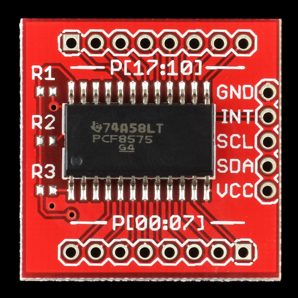
Have you run out of I/O pins? This great IC allows the user to expand up to 16 I/O using only two I/O for control! The PCF8575C is controlled through an I2C interface and features 16-bits of quasi-bidirectional input/output pins. Checkout the datasheet for more info!
Recommended Replacement: The SX1509 breakout is a 16 channel I2C GPIO expander. It's not drop in replacement but is a good functional match.
- 16 individually addressable pins
- Each pin configurable for input or output
- Interrupt output pin
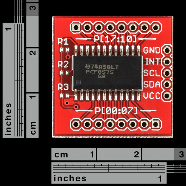
- 1" x 1"
- Schematic
- Eagle Files
- Information Page (PCF8575C)
- Datasheet (PCF8575C)
- Example I2C Project
- Example AVR code
- mbed Example
- GitHub (Design Files & Example Code)
SparkFun I2C Expander Breakout - PCF8575 Product Help and Resources
Core Skill: Soldering
This skill defines how difficult the soldering is on a particular product. It might be a couple simple solder joints, or require special reflow tools.
Skill Level: Noob - Some basic soldering is required, but it is limited to a just a few pins, basic through-hole soldering, and couple (if any) polarized components. A basic soldering iron is all you should need.
See all skill levels
Core Skill: Programming
If a board needs code or communicates somehow, you're going to need to know how to program or interface with it. The programming skill is all about communication and code.
Skill Level: Competent - The toolchain for programming is a bit more complex and will examples may not be explicitly provided for you. You will be required to have a fundamental knowledge of programming and be required to provide your own code. You may need to modify existing libraries or code to work with your specific hardware. Sensor and hardware interfaces will be SPI or I2C.
See all skill levels
Core Skill: Electrical Prototyping
If it requires power, you need to know how much, what all the pins do, and how to hook it up. You may need to reference datasheets, schematics, and know the ins and outs of electronics.
Skill Level: Rookie - You may be required to know a bit more about the component, such as orientation, or how to hook it up, in addition to power requirements. You will need to understand polarized components.
See all skill levels
Comments
Looking for answers to technical questions?
We welcome your comments and suggestions below. However, if you are looking for solutions to technical questions please see our Technical Assistance page.
Customer Reviews
4 out of 5
Based on 1 ratings:
PCF8575 breakout board
Works well, used it to scan a 4x4 keypad & still have 8 I/O pins left over. Interrupt means main program does not have to constantly poll keypad.
Pin connections:
SDA to pin 4 on the analog header
SCL to pin 5 on the analog header
VCC to 5v
GND to GND
I/O pins need pull up resistors to VCC.
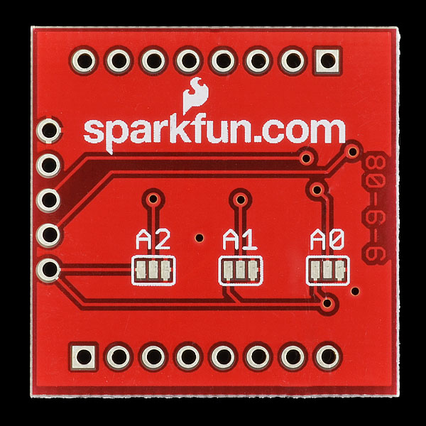
Board has A0-A2 with solder pads like (|). connect middle to left (power) for a 1, or right (gnd) for a 0. (see picture shown above)
setting the pins:
Wire.beginTransmission(d);
Wire.send(b); // byte for pins 0-7
Wire.send(b); // byte for pins 8-15
Wire.endTransmission(); // stop transmitting
The board supports id 0-7. Add 32 (0x20) to the id and pass that to beginTransmission. My device id was 0 and I passed 32 to beginTransmission
you have to send an even # of bytes. first is the lower 8 I/O pins. second is for the higher 8 I/O pins.
read is similar. here's quick code
Wire.requestFrom(32, 2); // 2 bytes from device 0
while(Wire.available())
{
char c = Wire.receive();
Serial.print(c, HEX); // print the character
Serial.print(", ");
}
you need to first write 1 to pins you would interested in reading from.
Sparkfun - Please retire this product! This is a BAD board design - very difficult to work with on a breadboard. The pin spacing (as noted in comments some 4 years ago!) are incorrect, and the SCL/SDA connections are in a very inconvenient/breadboard unfriendly location. In addition, the board size is such that it covers needed holes on a solderless breadboard.
My suggestion - if you are working on a breadboard is to NOT use this part. Get a 28-pin version from another vendor and an IC socket and you'll be good to go. Not to mention there are better chips from NXP and Microchip.
ARRGH! The board as received on 3/26/2015 has INCORRECT spacing between the left and right set of edge-holes. If I set a digital vernier to .800 and lay it along the holes - there is an OBVIOUS mis-match. Which means common .1 headers soldered in will be spaced wide and not go into a standard breadboard. By eye, it looks like the spacing is about .830. Yet another example of the "Fine QC" our Chinese friends are giving us - and that Sparkfun is sleeping at the switch and not doing a thorough QC on incoming parts!
Now I'll have to go back and check all the BOB's I've recently purchased... Sad.
Hi, please email techsupport@sparkfun.com and they can help you out as well as verify our current stock. Thanks.
I bought the Breakout-PCF8575, however I'm not sure how prepare it to interface it with the Arduino, in some datasheets the A0, A1 and A2 are wired to ground; SCL and SDA, I understand are connected to an Arduino port via pull-up resistor, my question is: Do I need to solder the pull-up resistors in your Breakout-PCF8575 in the R1, R2, R3 holes?
Additionally, do I need to make a connection between center pin and the right pin in every A0, A1, A2, if I want to have these pins to ground?
Thank you
Hi,
I need to read/write 16 I2C devices which have the same I2C address (0x68) using only one I2C port in my uC. Is possible to this with this product?
Thank you,
With Interrupt
Can someone please define the difference between the PCF8575 and the PCA9555? What I need is something that will simply give me additional I/O digital pins for my RedBoard. All of these additional I/O will have a bunch of sensors. I'll need to be able to change the address as I am already using SDA and SCL pins. Which version is easiest to work with? Which one has the best tutorials for the total Noob that I am?? Thanks
The PCF8575 only tolerates inputs at +0.5 Vdd, whereas the PCA9555 is tolerant to 6 volts, regardless of the supply. This means you can use it in mixed supply systems without level conversion. The 9555 also has more available total sink current, 200 mA compared to the 8575's 100 mA, while the 8575 has a lower supply current.
Another important note is that the 9555 has true bidirectional IO, which is selectable via a control register. The 8575 is quasi-bidirectional, which can cause issues when attempting to apply voltage to a pin configured as a low output. Check out Philips app note AN469 for a ton of great, readable information on the differences between various I2C I/O parts.
Does this expander also increase the distance that I2c data will transmit reliably?
No.
However, distance can be extended with some cleverness: http://www.nxp.com/documents/application_note/AN11075.pdf
It would be nice if more of these breakout boards were designed to mount directly to breadboards just by adding a few header strips. These boards were perpendicular pinouts make for more difficult development.
I am using the PCF8575 breakoutboard to connect 4 mpr121 boards. Without the PCF8575, the mpr121 code worked perfect. (http://code.bildr.org/download/1010.zip) However, I am having trouble to alter my arduino code to read the data when connected to the PCF8575. I guess the problem lies in the part of the code where the pins are adressed. In the original code I used Wire.requestFrom(0x5A,2); However with the PCF8575 board I need to alter the addressing within the code. I had a look at the sample AVR code, but this is rather complicated. Can anyone help me with the adressing of the pins?
Hello!
My only PCF8575 provides between 1.6 and 2.6 volts in output. The power supply is 5 V and have resistors of 10 K between sda / scl and VCC. Any suggestions to solve the problem being?
Best regards.
Wouldn't a simple DIP atmega8 with internal clock do the same job, for $2?
How many analog i/os are there?
Whoa!!! Where did this come from? I thought I would need a mux, and when I could
Save pins? This is going to be useful.
Could you please do a 3.3V version?
Just apply 3v3 to the board, then your good to go!
Lerche
I would like to note that the PCA9555N mentioned above has internal pull-up resistors. This chip and the PCA9535 appear to require external pull-up resistors.
Found an alternative
The PCA9555N is a 24 DIP (0.6 wide) - and there are other packages available, and this is a superset of the 8575.
As DBLEONARD says below- You have pull-up resistors built in with the PCA9555.
What that translates into if you are trying to make a x16 pushbutton keyboard is that all you need to connect all those x16 SPST switches is one side connected to ground and the other side connected to one of the PCA9555 I01_1 Through IO_7, or IO2_1 through IO2_7 lines.
This save you from having to make a 4 by 4 grid and having the Arduino Poll each of the x16 Switches and adding all those pull-up resistors. The PCA9555 handles all the de-bouncing, and sends an INT to your Arduino. That way the Arduino can be doing something more important than Polling Switches. NXP has a great example how this works in their LED dimmer demoboard on PG 5 Figure 2 >> http://www.nxp.com/documents/application_note/AN10315.pdf. COOL THING IT’S 5 V I/O tolerant.
I would like to point out IMO that NXP does a better job explaining how the PCA9555 (16-bit I2C-bus and SMBus I/O port with interrupt) works then does TI their version >> http://www.nxp.com/documents/data_sheet/PCA9555.pdf
One detail on the spec. sheet for the inexperienced to be aware of: the maximum GND and Vcc currents are 100mA.
To spell it out, this means that although each pin can deliver 25mA, if you really need this much current, you will only be able to run 4 outputs at a time. I got round this limitation with a bit of multiplexing.
Very nice little breakout and very easy to use.
Thank you very much, Tabouli. Your example code was very useful.
Similar chips, like MCP23017, have also a limited total current allowed (125 mA into VDD for microchip version).
If you really need that current then you can use trts or mosfets.
so everyone else knows, unfortunately the 0-7 side does not quite line up with the holes on a protoboard. :( shame if you ask me...
Time for a revison to fix the alignment and descrease the width by one column on a prototype board.
Not only that, but even if they did line up, the board is too wide to allow you to actually connect anything on one side of the breadboard. Makes it pretty much useless for breadboarding, which is kind of the point. This thing needs a new layout.
You could add in the features that up to 8 boards can be connected to the same bus thanks to the solder jumpers on the right of the board (ADDR mark).
Note for Arduino users : the pinning of power and I2C signals is compatible* with an Arduino board, thus you can plug this breakout board right in the 4 last analog pins of your board without any shield
(* as 'Tod' did with its BlinkM's package, a wonderful idea)
The AVR code example is much more complicated for such a simple device. In modern days, most every AVR developer uses code library for I2C communication, thus a simpler code using AVRlib C lib or Arduino Wire code would be better.
I could write some examples if I had one this breakout board :)