- Home
- Product Categories
- Development Tools
- PICAXE 18 Pin Standard Project Board

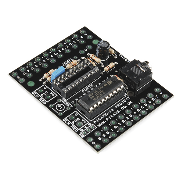
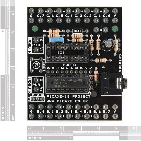
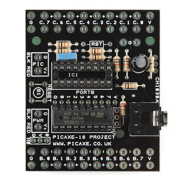
PICAXE 18 Pin Standard Project Board
Simple project board for 18 pin PICAXE controllers. Includes 8 channel Darlington driver for buffered outputs.
Note: Our latest shipment of these boards have an error. The error is remedied by soldering in a small jumper wire (or solder jumper) and only affects those needing to use the B.0 output. The new revision of this board will ship without this error. You can view the instructions here.
PICAXE 18 Pin Standard Project Board Product Help and Resources
Core Skill: Soldering
This skill defines how difficult the soldering is on a particular product. It might be a couple simple solder joints, or require special reflow tools.
Skill Level: Rookie - The number of pins increases, and you will have to determine polarity of components and some of the components might be a bit trickier or close together. You might need solder wick or flux.
See all skill levels
Core Skill: Programming
If a board needs code or communicates somehow, you're going to need to know how to program or interface with it. The programming skill is all about communication and code.
Skill Level: Competent - The toolchain for programming is a bit more complex and will examples may not be explicitly provided for you. You will be required to have a fundamental knowledge of programming and be required to provide your own code. You may need to modify existing libraries or code to work with your specific hardware. Sensor and hardware interfaces will be SPI or I2C.
See all skill levels
Core Skill: Electrical Prototyping
If it requires power, you need to know how much, what all the pins do, and how to hook it up. You may need to reference datasheets, schematics, and know the ins and outs of electronics.
Skill Level: Noob - You don't need to reference a datasheet, but you will need to know basic power requirements.
See all skill levels
Comments
Looking for answers to technical questions?
We welcome your comments and suggestions below. However, if you are looking for solutions to technical questions please see our Technical Assistance page.
Customer Reviews
No reviews yet.
Can the Darlington driver switch 120v AC to cycle LED Christmas light strings on and off?
Definitely not ! But, you could drive the coils of up to 8 relays (or even 1 relay using all 8 outputs in parallel if the current draw is high enough) which, in turn, could switch the 120 VAC. The ULN2803 driver IC is an excellent relay driver, with built-in free-wheel diodes.
I have created three control modules for 24 Christmas light circuits (controlling about 10,000 LED lamps) For each module, I made another board that incorporate 8 solid state relays. The Darlington driver easily controls (switches) the solid state relays (bought from Spark a Fun) that I soldered to the female end of outdoor 18 gauge green extension cords. Having learned from the first one, cut the cords so that you have 3-4 feet of lead to work with. I mounted everything into a plastic Thermous brand lunch pail that I sealed th holes for the handles. I s filled a hole in the side of the bottom of the box for the leads to exit and sealed everything. I had to write the program on my MacBook for various lights and program them. If I decide to change something, I just make the changes on my MacBook, then carry it out to the controller and overwrite the existing program in less than a minute. These work Awesome!
The latest board I received had two mounting holes. I found PCB corner mounts that work well with the other / older boards that don't have mounting holes. Sparkfun would likely benefit from carrying these types of PCB mounts as well. I searched for "Corner / Edge - Screwmount Circuit Board Supports" and found them at www DOT futureelectronics DOT com/en/Technologies/Product.aspx?ProductID=TCEHCBS1001RICHCO5646682.
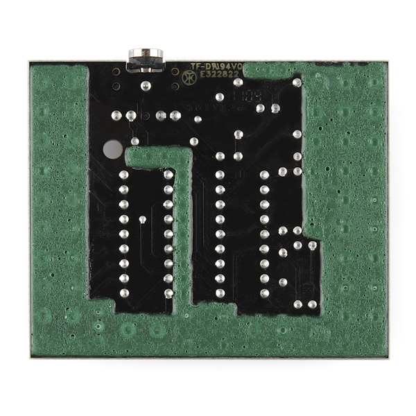
What is the green stuff on the back? Appears that I would have to scrape it off to solder on the crew terminals. Is that right?
I wish the PCB had 4 holes at the corners for mounting it.