- Home
- Product Categories
- Development Tools
- Spartan 3E Breakout and Development Board

Spartan 3E Breakout and Development Board
Replacement: None. We are no longer building this board. This page is for reference only.
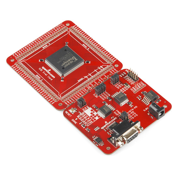
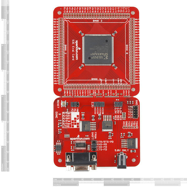
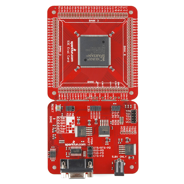
The Spartan-3E Evaluation card is a full breakout of almost every pin of the Spartan 3E 500,000 gate FPGA in a PQ208 Package. Also provided are the 3 power supplies, an AT45DB161D SPI prom to store the FPGA configuration image, and a RS232 level shifter for easy serial communications. RS232 and power board can be sheared off for a completely isolated breakout board. Comes with a 50MHz oscillator.
- Schematic
- Eagle Files
- Datasheet
- Python Script (bin) (dev)
Comments
Looking for answers to technical questions?
We welcome your comments and suggestions below. However, if you are looking for solutions to technical questions please see our Technical Assistance page.
Customer Reviews
No reviews yet.
It has taken a while to get back to this board. I have three Digilent Nexys2 boards, and they are great to use with all the "test hardware", but for sheer FPGA pinout availability, this Sparkfun board is hard to beat.
I have the parallel port programmer from SF, but I also just got a Xilinx USB Platform Cable from a Chinese vendor for $60 via ebay, and it just programmed this board fine, using ISE Webpack 11.1. I tried to buy it from Hummingosand, but after two months it never came - check the seller feedback! Second order went to hongkong_electronics, it took about two weeks to arrive.
I'm using the "flying leads" cable right now, but can program both the FPGA directly, and the onboard flash AT45DB161D(although the flash hangs at the end).
For those that cannot use a parallel port any longer, and can figure Impact out, this USB programmer will work. Now, off to try adding the SF Wiznet 830 module to the SF FPGA board...
Terry
Ditto on Hongkong_electronics. Have placed two orders and both canme in about 10-12 working days.
Was this the item that you got from them?
EDIT: So it turns out that firefox has blocked the ebay page because of fraudulant activity.
http://cgi.ebay.com/ws/eBayISAPI.dll?ViewItem&item=200538724085&ssPageName=STRK:MEWAX:IT
Do you have a link to the USB programmer product you're referring to?
Can I program this with the serial port provided on the dev board?
This answer to this is "Sorta"
Sorta?
Any chance of seeing a basic project example for this board? There are a tonne of possibilities for this dev board, but I think many of us who are new to FPGA could use a bit of a push in the right direction. Perhaps even something as simple as a basic project for the freely available Xilinx ISE Webpack that shows basic I/O.
I'm trying to make a project now using the Base System Builder, but because I need to specify all the hardware on this board (serial, etc.), I'm a bit lost. Is there anyone at Sparkfun who has some basic experience with FGPAs?
How do you want to program things? You can do it one of three ways in the Webpack. These are schematic, VHDL, and Verilog.
no replacement?! come on, yer killin' me, Smalls!
I'm dusting this one off again after a couple of months and I had a question regarding the onboard 50mhz oscillator. From the schematic it looks like it might be U12 which is tied to p181 on the FPGA. I need this information to set the proper pin out. My test design, which is a simple counter, doesn't seem to be working and I don't have a scope right now to check things out.
Yes. Define the oscillator as P181 in the UCF file and as an input in your code. Things should work.
JTAG HS1 Programming Cable ,
JTAG USB Cable
can either of these cables be used to program this board?
which one is better?
How about some eagle files? I'd like to add an arduino chip and xbee for a project I have.
Thx
With this board, you are down to the basics. Nothing but the gate array, voltage regulators, the prom, RS-232 level converters, and an oscillator. Digilent boards are good if you want switches, buttons, LEDs, and 7-segment display. OpalKelly boards are more focused on the gate array and bring out more pins without much clutter. GadgetFactory Papilio boards look like good starters (I don't have one). This Sparkfun board brings out EVERY pin with no clutter at all. It provides control over the individual bank VCCO voltages. Many boards won't let you experiment with LVDS at 2.5V, for example. This one does.
The prom is not on the JTAG chain, which seemed inconvient to me at first, but it has advantages. It makes the prom more easily accessible by the FPGA and/or an external device. The prom is 16 Mb, but the bit file uses only a little more than 2 Mb. All that additional prom space is available for any purpose.
If Sparkfun is going to continue this product, it would be nice to post a link to an example UCF file. It's not hard to generate the file from the schematic, but it would save a step and lower the barrier for some users.
This board is red now, not green.
I accidentally stumbled upon this card, seems to tick all your boxes for features lacking on this board.
How would I interface this board to a 5V cpu?
I'd like to implement peripherals on the FPGA and will need a address and bi-directional data bus...
So far I'm looking at something like a 74AHC245 or one of its friends.
Any clues?
Ti and linear have high speed bi-directional level shifters for $1-2 a chip (8 lines), or you can buy the TI one from sparkfun preassembled. Connect the HV to the 5v power supply, and lv to the FPGA i/o voltage which is usually 3.3 on most older generation FPGAs currently produced, so I beleive it is here too.
I'm not sure about interfacing to a 5V CPU.
You can create address lines and bidirectional data lines with the FPGA pins themselves. Declaring wires/registers as INOUT allows pins to be bidirectional, under control of the FPGA, or via a separate direction pin into the FPGA. I use INOUT to interface bidirection data to memory devices external to the FPGA.
Is that what you mean?
Terry
Hi, Can someone give me the exact dimensions of the board please ? .
The two-part board is approx 3-3/16 wide by 6-1/4 long, with the FPGA part being 3-1/2 long. The two boards can be cut apart, but then you need to supply power regulation, flash, etc.
Terry
Thank you.
I absolutely see NO reason in buying such 2 layer board with FPGA for 100$!! When u can add 50$ and buy good quality Spartan3E from digilentinc... OR.. if u dont have much money, but want to start tinkering with FPGA, here is the thing for starters:
http://www.altera.com/b/nios-bemicro-evaluation-kit.html
USB FPGA module.. from Altera, for 50$ only, with good signal quality :) Sparkfun: It would be much better to see something more original, or at least something what would really make a good deal! What about 4 layer FPGA + Wi-Fi? or something like that? for reasonable price of course.. then it would be completely different! and worth the money!
I own a Digilent board, and it's great, since it is easy to program and has a bunch of buttons, switches, and LEDs. But I bought one of these SFE boards specifically because it does not have those buttons, switches, and LEDs. I don't need them and I'm already short on I/Os.<br />
<br />
The Digilent boards are better for learning how to use FPGAs, but the SFE board is better for an actual project.<br />
mws,
Could you please give some information about your setup with this board? Was programming this board straight forward? Did you use Xilinx ISE and iMPACT? Any help would be much appreciated.
I seem to recall that this is actually 4 layer board.
The digilent board is DEFINITELY a better deal if you are learning to interface FPGAs to peripherals. Even if you only want to learn FPGAs by themselves, it's a far better deal.
The benefit of the Sparkfun board is size. It's great for small projects. However, due to the lack of tutorials and examples from Sparkfun (and others), I foresee many unhappy customers.
Why is there no SPE reply to these questions? I am an active FPGA developer, but I hesitate buying this because the lack of support. SPE, please respond. All we want is an easy way to program this FPGA and PROM.
*SFE
I just got my DEV-08458 Board and the Xilinx Parallel Programmer. I have installed ISE Webpack 10.1 and as far as I know, It does not support the Parallel Programmer III or its clones. How do I get around this? How do I programme the Flash in Indirect SPI mode using the Xilinx Parallel Programmer?
Is there any chance you could post the Eagle files?
Also, are there any plans for a usb programmer?
Ok. The SPI flash is getting programmed finally.
The trick is to use impact of ISE 10.1 and use the indirect SPI programming.
ISE 9.2.4i does not support indirect SPI programming for this chip/board.
I am not able to program the AT45DB161D on this board using
1) Indirect SPI (with Impact 9.2.4i with USB cable)
Does ISE9.2.4i support Indirect SPI for XC3s500e ?
2) Direct SPI (with a header soldered to the Flash chip)
Gives error -> Impact 2595 "device validation terminated"
3) Downloaded and tweaked the S3ESK Picoblaze Serial port programmer from Xilinx website. This is meant for M25P16 flash on the EDK board. so in spite of serial port saying "OK" after dumping the mcs file, all the locations were blank (0xFF).
I guess its the different command set that is causing problem.
4) The "load_prom.sh" in the attached Python script gives an error of "xilprg" command not found.
I am using ISE 9.2.4i with USB prog cable.
The XC3S500E is getting detected and a sample LED blink bit file is working. but i am not able to program the AT45DB161D.
Any ideas ?
I bought the mach4064 dev board from xgamestation. It has the ability to program other devices via an eight pin ribbon cable taken off the board. Will that work to program this board?
Correction, the mach4064 has a 10 pin header and cable for programming other devices, not 8 pin as I originally stated.