- Home
- Product Categories
- Development Tools
- FTDI Basic Breakout - 3.3V

FTDI Basic Breakout - 3.3V
Replacement:DEV-10009. The new version does not have the 6-pin header. This page is for reference only.
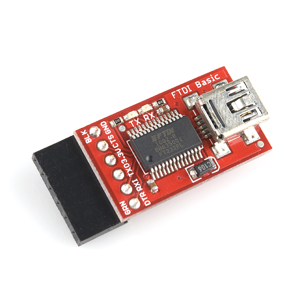
This is a basic breakout board for the FTDI FT232RL USB to serial IC. The pinout of this board matches the FTDI cable to work with official Arduino and cloned 3.3V Arduino boards. It can also be used for general serial applications. The major difference with this board is that it brings out the DTR pin as opposed to the RTS pin of the FTDI cable. The DTR pin allows an Arduino target to auto-reset when a new Sketch is downloaded. This is a really nice feature to have and allows a sketch to be downloaded without having to hit the reset button. This board will auto reset any Arduino board that has the reset pin brought out to a 6-pin connector.
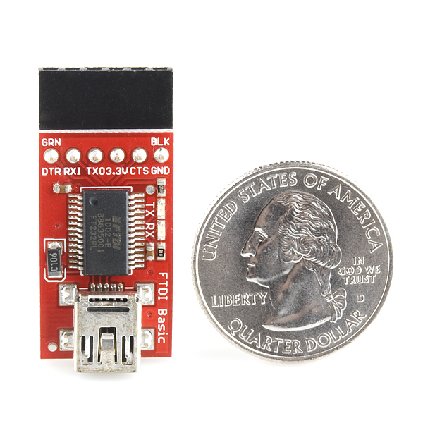
The pins labeled BLK and GRN correspond to the colored wires on the FTDI cable. The black wire on the FTDI cable is GND, green is DTR. Use these BLK and GRN pins to align the FTDI basic board with your Arduino target.
There are pros and cons to the FTDI Cable vs the FTDI Basic. This board has TX and RX LEDs that allow you to actually see serial traffic on the LEDs to verify if the board is working, but this board requires a miniB cable. The FTDI Cable is well protected against the elements, but is large and cannot be embedded into a project as easily. The FTDI Basic uses DTR to cause a hardware reset where the FTDI cable uses the RTS signal.
This board was designed to decrease the cost of Arduino development and increase ease of use (the auto-reset feature rocks!). Our Arduino Pro and LilyPad boards use this type of connector.
FTDI Basic Breakout - 3.3V Product Help and Resources
How to Install FTDI Drivers
June 4, 2013
How to install drivers for the FTDI Basic on Windows, Mac OS X, and Linux.
Comments
Looking for answers to technical questions?
We welcome your comments and suggestions below. However, if you are looking for solutions to technical questions please see our Technical Assistance page.
Customer Reviews
No reviews yet.
This board seems to have been updated, i just received this today:
http://www.flickr.com/photos/28914418@N02/3830391399/
http://www.flickr.com/photos/28914418@N02/3831178226/
I just realized I posted the comment on the hook ups on this product but I used the 5V version. Not sure if there is any difference .. just a note.
What a great product. Being brand spanking new it took me a bit to figure out all the details on how to use this on a breadboard and a chip / crystal only.
This was a great start ...
http://itp.nyu.edu/physcomp/Tutorials/ArduinoBreadboard
1) To get started quick, just hookup the Vcc and Ground from the breakout to the breadboard and you can skip the regulator part of the tutorial.
2) Once you have the chip wired on as shown in the tutorial ... remove the pin 1 run connections and setup the pins as follows:
PIN -> Connection to make
DTR -> through a .1 cap then to pin 1 on the chip
RX1 -> to the Tx on chip (pin 3)
TX1 -> to the Rx on chip (pin 2)
5V -> to power in on breadboard
CTS -> to ground on breadboard
GND -> to ground on breadboard
3) Now Arduino with the Duemilanove (328) setup should work.
Note: I had issues running 0016 but 0015 runs fine (xp and windows 7)
If I did anything stupid and/or am passing on stupid advice please correct me.
I have two of these 3.3v versions which I got in the past few months and they look ALMOST identical to the 5v version (which are NOT in stock as I write this).
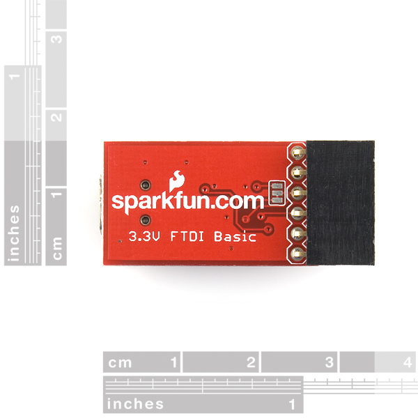
Looking very close at the bottom, (look at the 5v picture, not the one for this page) you can see the shorting pads, and on mine the default short is to the other pad. So to make it 5V I assume that all I would need is to cut and short just like the 5v breakout, but the opposite set.
Looks like it would be pretty easy to modify for 5V - just remove the short SJ1, bring a jumper from the 5V side of C2 to the U1 side of SJ1, cut the 3.3v trace on the bottom near pin 4 of JP1 and bring another 5V jumper to that pin.
Couldn't you just cut the trace between the left and middle pads (headers pointing down) of SJ1 and short the middle pad to the right one (see photos of back)?
Confirmed. I made this modification and the 5V Vcc was correct. Sketch upload worked on the first try.
The SJ1 is the blob of solder near the DTR label. I cut the trace between SJ1 and the capacitor instead of removing all the solder from the SJ1 itself. I cut the trace to JP1 Pin4, and used the SJ1 and the C5+ pole as convenient solder points (C5+ instead of C2+ since it's larger).
FTDI Basic Breakout 5V Mod picture
To clarify, http://whosawhatsis.com/paraphernalia/ftdi_basic_5v.jpg
Shouldn't it also work if you only connect C5+ to SJ1 and cut the trace on the reverse on the other side of the branch? Or is C1 rated below 5 volts? Even if it is, you could cut its trace to ground and be left with two cuts and one patch, rather than 2 of each...
My mac doesn't see the this device. My TX and RX lights are constantly lit. Any advice? Thanks!!
I think that means that the VBus pin on the FT232 is getting power but the device has not enumerated on the USB hub or something like that. There might be a solder bridge or lousy trace somewhere.
If you like, contact techsupport@sparkfun.com about having the item returned for testing.
It would be nice to actually know how much power is available at the 3.3V pin. That said, it works quite nicely to test out a 3.3V TTL device if you want to connect it directly to a PC. I've used it for hacking together an interface to a GPS unit @ 50 mA. It works fine. Probably not a recommended use but it certainly is nice for prototyping.
I want to program a pluto FPGA which this. Apparently I'd need to invert the TxD bit but not the RxD bit because it's asynchronous, any idea what this means?
This board worked for a few hours, but now Windows no longer recognizes it. When I plug it into my computer, the Rx and Tx lights blink together a few times, and Windows loads it as an "Unknown Device". I've tried two Windows computers, and also on Ubuntu 9.04 with no success. Any ideas as to what could be wrong? Thanks for any help!
I'm having a similar issue on a board I've made. The chip works fine for a while, and then all comms stop. The Rx LED just blinks for a while, and then stops. When I unplug and reconnect the device it gives me an 'Unknown device' error. If I let the board sit for a few hours and plug it in again, it works fine for a bit, and then I face the same problem. How is this possible? Either the chip is damaged or not!
Reset tied to Vcc; Test grounded.
Smoked it ! Probably Static Zap. I apparently did the same thing.
The lights just flash in unison and the PC never finds the usb serial port. Its not a driver problem since other FTDI devices are working just fine.
If there is a reset, I don't know about it.
You guys really need to sell a 1x6 to 2x3 cable so we can use these for reprogramming the Duemilanove without having to use a handful of jumpers.
Is there a version of this that is 3.3v and 5v in one pcb that is changed via jumper?
It looks like this board has been modified to be identical to the 5V board, except with the trace in the 3.3V position instead of the 5V position. From medecau above: http://www.flickr.com/photos/28914418@N02/3831178226/
Howdy,
Just to be sure... this is basically an FTDI 3.3v cable, right? so i can use it to connect to a XBee adapter (from Adafruit)?
Steph
just found this thread on a search;
I don't think the 3.3v or 5v will work with the ADAFRUIT XBEE adapter. (Somebody please correct me if I'm wrong here)
Using X-CTU I can read the Xbee but not update the firmware. suspicion is currently with this bit;
"The major difference with this board is that it brings out the DTR pin as opposed to the RTS pin of the FTDI cable".
Works fine with Arduino mini pro, Boardudino etc but looks like I'm still going to need the FDTI cable... :-(
Looked at the Adafruit adaptor and I think you're right. It surely does look that way.
Haven't tried it myself but looks like a great idea to use for testing the XBee command set. I'm using breakout boards and USB deelopment boards, but your idea looks like a solution that will work just as well.
They've just implemented this with a simple 5V jumper, and it costs $5 less!
http://www.sparkfun.com/commerce/product_info.php?products_id=9115
Whosawhatsis: Shouldn't it also work if you only connect C5+ to SJ1 and cut the trace on the reverse on the other side of the branch? Or is C1 rated below 5 volts? Even if it is, you could cut its trace to ground and be left with two cuts and one patch, rather than 2 of each...
I need to make this mod and wondered if this one is 100% certain? Thanks
Hi,
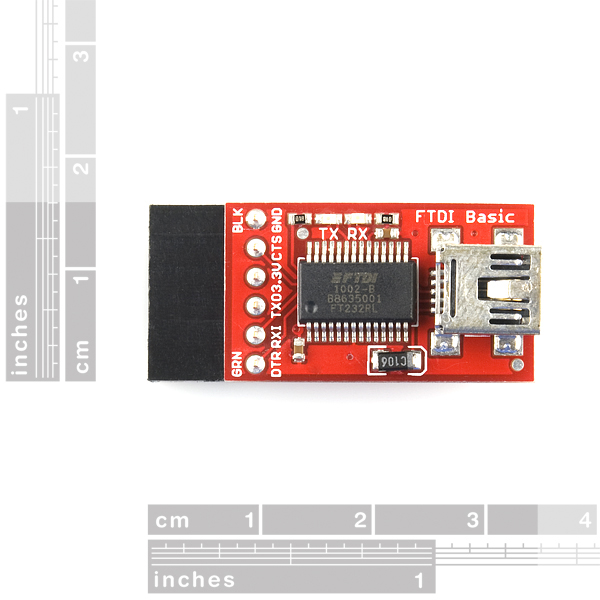
I'm looking at the Schematic and the Pinout is:
GND-CTS-3.3V-TxO-RxI-DTR
But in the board the pins are labeled like:
GND-CTS-3.3v-RxI-TxO-DTR
Why are the tx/rx pins toggled?
That's probably because TX talks to RX and RX listens to TX. Basically, it's a question of whether it's denoting its own TX/RX lines, or those of the mating connector.
is this a 5v or 3.3v?
It is a 3.3 Volt product, But you can modify the product to run off 5.0 Volts.
how do i modify it for 5v?
Quoted from AdamDavis
"Looks like it would be pretty easy to modify for 5V - just remove the short SJ1, bring a jumper from the 5V side of C2 to the U1 side of SJ1, cut the 3.3v trace on the bottom near pin 4 of JP1 and bring another 5V jumper to that pin."
Don't know if this works of not tho. But it should
Will this work with the Parallax Propeller?
Recognized properly as ttyUSB0 on first plug-in, by Ubuntu 8.04. No fiddling with configs or drivers was necessary.
What are the Arduino Pro boards ? AVR32 maybe ? Something along the lines of the OMAP Beagleboard but using the Arduino IDE I would hope.