- Home
- Product Categories
- Development Tools
- Arduino Pro Mini 168 - 3.3V/8MHz

Arduino Pro Mini 168 - 3.3V/8MHz
Replacement:DEV-09219 and DEV-09221. This has been replaced with a new version with the ATmega328. This page is for reference only.
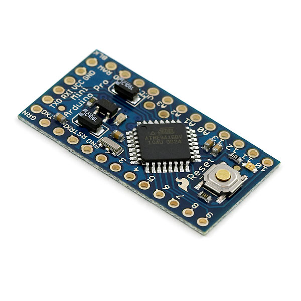
It's blue! It's thin (0.8mm)! It's the Arduino Pro Mini! SparkFun's minimal design approach to Arduino. This is a 3.3V Arduino running the 8MHz bootloader (select 'LilyPad' within the Arduino software). We added a handful of features to become a fully certified Arduino board.
Arduino Pro Mini does not come with connectors populated so that you can solder in any connector or wire with any orientation you need. We recommend first time Arduino users start with the Diecimila. It's a great board that will get you up and running quickly. The Arduino Pro series is meant for users that understand the limitations of system voltage (3.3V), lack of connectors, and USB off board.
We really wanted to minimize the cost of an Arduino. The Arduino Pro Mini is like the Arduino Mini (same pin out) but to keep the cost low, we used all SMD components, made it two layer, etc. This board connects directly to the FTDI Basic Breakout board and supports auto-reset. The Arduino Pro Mini also works with the FTDI cable but the FTDI cable does not bring out the DTR pin so the auto-reset feature will not work.
Can't decide which Arduino is right for you? Arduino buying guide!
**Note: **A portion of this sale is given back to Arduino LLC to help fund continued development of new tools and new IDE features.
- ATmega168V running at 8MHz with external resonator (0.5% tolerance)
- Low-voltage board needs no interfacing circuitry to popular 3.3V devices and modules (GPS, accelerometers, sensors, etc)
- USB connection off board
- Supports auto-reset
- 3.3V regulator
- Reverse polarity protected
- DC input 3.3V up to 12V
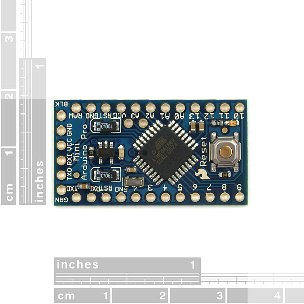
- On board Power and Status LEDs* 0.7x1.3" (18x33mm)
- Less than 2 grams
Arduino Pro Mini 168 - 3.3V/8MHz Product Help and Resources
How to Build a Remote Kill Switch
May 31, 2016
Learn how to build a wireless controller to kill power when things go... sentient.
LED Cloud-Connected Cloud
February 22, 2016
Make an RGB colored cloud light! You can also control it from your phone, or hook up to the weather!
Comments
Looking for answers to technical questions?
We welcome your comments and suggestions below. However, if you are looking for solutions to technical questions please see our Technical Assistance page.
Customer Reviews
No reviews yet.
Any chance of you making the other 2 ADC channels (ADC6 & 7) available to us? It seems a waste to do nothing with 2 good pins.
They Are. They are SCL and SDA for the I2C data bus. Look just right next to the 'mega168 and they're there.
No ... look at the schematic. The I2C are ADC pins A4 and A5. The pins I am talking about are ** not ** broken out. Again, look at the schematic, A6 and A7 go no where.
apologies... (google was my friend)..
Google is everyone's friend :-)
Probably a silly question but can I program this the same way as the Arduino Mini? Or do I need an FTDI cable?
thanks!
http://www.arduino.cc/en/Guide/ArduinoMini
Just got round to actually using this part...
Of course the ATmega168V is happy running at 5V (from the USB supply on the "3.3V" FTDI cable from Adafruit), so no worries there.
I managed to identify the board by getting a magnifying glass out and checking the regulator and xtal ("3.3", "08").
I guess you just need to avoid having a supply connected to the RAW input when connecting the FTDI cable, since the power from USB is connected straight to Vcc...? Would it matter that the reg was trying to put out 3.3V while Vcc is at 5V?
What's the default sketch that comes loaded on these? I managed to break my FTDI breakout board trying to get it hooked up to this, so I can't load sketches yet. I powered the board from ~6v on RAW. What I assume is the pin 13 LED starts to blink slowly, then faster and faster until it is on solid. Then it turns off and starts over. This is just different than the standard preloaded 'blink' sketch that comes on the Duimilanove, and I wanted to make sure the board is working ok, and not freaking out on me. :)
default sketch in mine was like yours: blink, but speeding up in a loop and then starting slow again. cute :)
i have the same problem and it wont upload a new sketch.. please help!
Are you able to modify this to run at 20MHz? If so, how? thnx in advance.
What is the maximum current draw? 40 mA as per the current on the I/O pins?
Are there no pull-ups on a4 and a5? Running into some issues with TWI and would really appreciate a timely clarification on that.
Incidentally, they're spectacular boards. Really great for embedding into prototypes in the pre-PCB stage.
Never mind. Figured it out. Thanks. Stupid question, given that the pull-ups are internal to the ?C.
Seriously though, this project is gonna' blow all your minds ;-)
Keep those parts comin', Sparkfun!
Hi, how can I connect this with XBee? I have some problems maintaining the voltage at 3.3V. Currently I connect the Tx to the DIn directly... is it correct?
Rgs
Zhang Jie
Talking about a "3.3V" FTDI cable is quite confusing....
I have an FTDI cable here which is identified as "TTL-232R-3V3", but it's only the signals that are 3.3V, while the power line (red wire) is still 5V.
So according to the schematic for the Pro Mini/3.3, I can't connect this cable to the header because Vcc would then be over-voltage.
Correct me if I'm wrong, but it seems I need to make an adapter for the FTDI cable that brings this 5V line into the RAW pin instead, so it comes in via the regulator?
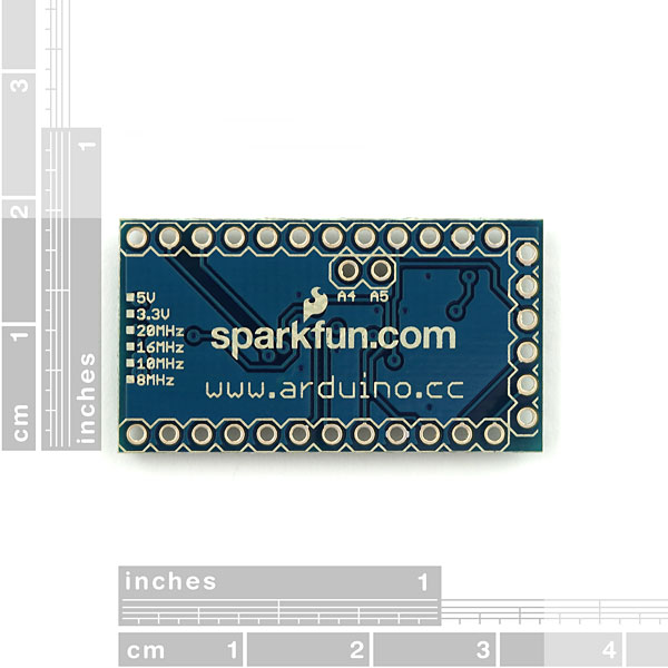
Also the silkscreen on the underside isn't marked in any way (it lists all options), so there's no way of identifying this device as being 5V or 3.3V? Was somebody supposed to put a checkmark in one of the white boxes to identify voltage and clock speed?
thanks
Where can I find a SMD crystal like that? Part #???
Hi - it's a Murata resonator, available at Digikey (490-1195-2-ND) and Mouser (CSTCE8M00G55-R0).
What happens if you plug in both raw power and usb power to the Pro Mini? Does it automatically sense and switch to the higher potential source of power like the Nano? How does the Pro Mini cope with 12V DC input, is that an absolute max or a recommended upper limit? I.e. is it safe to run it from an 12V DC wall wart?
I would hook both up at the same time, and disconnect things if things get hot - but that's just me. assuming you use our 3.3V FTDI Basic board (not 5V FTDI cable!), you should be fine.
I've pushed the voltage regulator up to 20V. It got toasty and started to internally shut down, but it survived and behaved normally when I brought it back to 12V. So 12V is the recommended limit, but should survive 16V ok.
How much does the Arduino Pro Mini weigh? I'm investigating throwing one on a tiny indoor RC plane...
Less than 2 grams. The scale said 1-2g but it wouldn't settle.
I found out what the GRN and BLK holes were for, they correspond to the black and green wires on a usb-rs232tottl convertor cable, for arduino the autoreset and a ground connection.
Yep - those are indicators that match the colors of the wires on the FTDI cable or on our FTDI Basic breakout board. That way the user can align the FTDI board with the correct pins.
What is the purpose of the legend on the underside of the board that shows boxes next to the labels 5V, 3.3V, 20 Mhz, 16 Mhz, 10 Mhz, 8Mhz?
We're hoping to release additional derivatives - different MHz, different main voltages. The silkscreen boxes will identify what is loaded onto the board.
I was wondering what the GRN and BLK holes were for (ground is GND)
This is a fantastic Board. I bought it as an opener to arduino after several years on vex gen 1, and 2 picaxe uC's The design and over operation is fantastic, flawless on my intel based mac running 10.5.4 leopard
The FTDI cable would work with the Pro Mini if the CTS pin was connected to reset with a .1uF cap (like this: http://www.flickr.com/photos/soundanalogous/2799232109/). Maybe that would make it incompatible with the FTDI Basic breakout board though.
The FTDI cable will work with the Mini Pro, but Arduino IDE currently only supports reset over DTR. We could add a connection to Reset and CTS through 0.1uF cap but I'm worried that would lead to possible erroneous resets.