- Home
- Product Categories
- Sensors
- Fingerprint Scanner

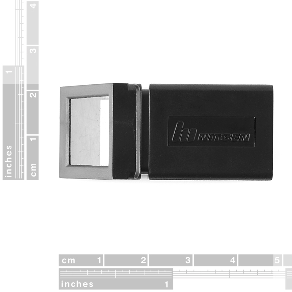
Fingerprint Scanner
Replacement:SEN-11792. This product has been discontinued by the manufacturer. This page is for reference only.
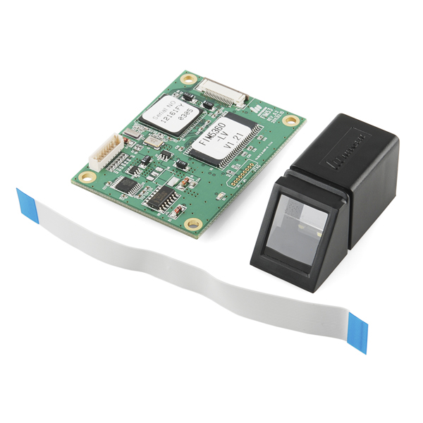
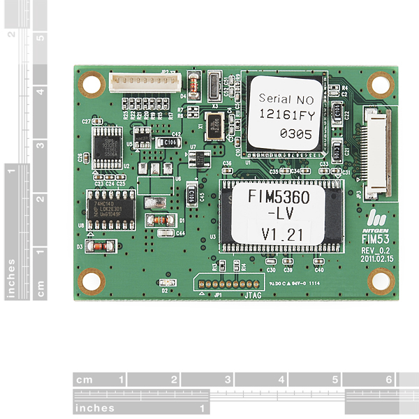
The Nitgen RS232 serial fingerprint scanner is a powerful ADSP-BF531 Blackfin based system. This scanner is capable of gathering and storing unique finger prints. Simply hold your finger on the optical scanner, query the device over serial, and you will be issued a unique ID. Use that ID within your embedded system to determine access levels, time clocks, door locks, etc.
Unit includes master controller board, optical reader, and ribbon cable to connect read to controller. We are trying to get pigtail interface cables made but in the interim, you will need to create your own connection to the serial connector.
Note: There was a time when we were selling both the FIM3040N-LV and the FIM5360N-LV. We have now phased out the 3040 and will be continuing to sell only the 5360. For those of you who have the 3040, we've listed the datasheet and interface guide below for reference, along with their model numbers. Any new orders should receive the 5360 so be advised to refer to the correct datasheet.
- Serial at 9600bps
- 3.3V@200mA
- Capture in 0.2s
- Verification in 1.0s
- Datasheet (FIM3040N-LV)
- Serial interface (FIM3040N-LV)
- Datasheet (FIM5360N-LV)
- [Serial Interface](http://cdn.sparkfun.com/datasheets/Sensors/Biometric/EN FIM ComProtocol V2.01.pdf) (FIM5360N-LV)
Comments
Looking for answers to technical questions?
We welcome your comments and suggestions below. However, if you are looking for solutions to technical questions please see our Technical Assistance page.
Customer Reviews
No reviews yet.
Hello everyone I just bought this finger print scanner(FIM5360) and I'm trying to use it with a netduino plus(could be an arduino as well) and I have no idea how to start, the datasheet is not very enlightening not to say is almost useless. So I wanna know some of you guys have any kind of test code that I can use?
Do I have to use the max232 to communicate with the micro-controller or Can I just use it directly? I really hope some of you can help me I'm totally lost(you can email me to randyjp125@gmail.com)
I have the same problem! Hope we can get some help ASAP
Have 5360 module, disaster of a thing.
It decides when it wants to connect to my MCU rather than when I want it to. It connects to my MCU every so often, When I connect it to EVTools (Nitgen software package for comms with module) it cant connect fast enough. Yes I have tested my MCU and yes it is sending correct 25 byte packet through serial port (checked with Realterm) yes baudrate is correct, yes 3.3V and ground, TX/RX are connected. Yes I have tested it with second module and same issue
Been working with it all day to improve my programme to work with it, but minute I disconnect it takes 2 weeks to reconnect. Very frustrating, especially when it costs so much..........
Where did you get EvTools from, my own device did not come with it
http://www.nitgen.com.br/downloads/softwares
This works great. Very easy to use. I have it connected to a shotgun lock I bought.
Ready, I know how to use it ... If anyone has any doubts, can write me to the following email ... josedanielvargas@gmail.com
Hi,
I'm very new to this whole subject area, but am after some advice before I buy an inappropriate device. I've just started looking at using a fingerprint scanner as a means of authenticating a motor starter system run from a Windows 7 computer rather than a microprocessor. Could anyone advise me whether this scanner is suitable for use on a computer together with the software and additionally what method can be used to then provide an electrical output for the PC should there be a positive authentication attempt.
Any advice would be greatly appreciated.
Hi guys!
What software should I use to communicate with the FIM3040N-LV after interfacing it to my PC? Because I want to create a database for attendance register using the finger scanner.
I have no trouble hooking up/controling this via RS232 my issue is that it will not reliably recognise fingerprints. sometimes i have to try 5-10 times before i can register/authenticate a print. sometimes it works on the first try. Any suggestions on how to adjust the the brightness/contrast/adaptive settings to get better reading of a print?
Ready, I know how to use it ... If anyone has any doubts, can write me to the following email ... josedanielvargas@gmail.com
are you using assembly.....are you interfacing to an 8051 microcontroller
No VB6 but that has nothing to do with the problem. I can control it just fine. I just kept getting more Fails than Accepted. Problem turned out to be i was just not pressing my finger to the glass hard enough to get a good quality read. If anyone has info on how to convert the raw image data from the sensor to an actual bmp that would be great. Soon i will connect it to a c8051f120 running a RTOS which will function as fingerprint engine start...
i can't program it, someone can't help me? aim new in program things
The datasheet for FIM5360 mentions that there is a /RESET pin to reset the device but I do not see one anywhere. Is this a misprint in the Datasheet itself?
I also found 2 or 3 different versions of the datasheet for FIM5360...Anyone abl to track down the latest version of the Data sheet? The board that I just received says Rev 0.2 and Firmware v1.20.
I talked with the company and the reset button has been removed from the FIM5360 and instead it is the power connections.
Hi,
I am using the FIM5360-LV module in a project and was already able to work with it by using pins 6, 7 and 8 to store/delete/verify fingerprints, and pins 4 and 5 to see the results of those operations. My problem is when I try to work with it by using the RS232 interface, I have correctly connected the RX and TX pins has it appears in the datasheet, but when I send the CMD_REQUEST_CONNECTION, has it appears on the serial communication protocol document, the module doesn’t respond anything. I’m using the following configurations to communicate with the module:
* No parity;
* No software control;
* No Hardware control;
* Open for reading and writing;
* Baudrate 9600;
* Data bits: 8;
* Stop bits: 1;
Can anyone explain me how to establish the serial communication with the module and help me out in this issue?
Thanks.
Any luck? We're having the same problem....
According to the block diagram in the data sheet is says that the module contains a TTL UART interface, with signals RxD0 and TxD0. Can anyone point to me how to connect to this interface? I don't see pins designated for these signals, please help.
Hi, I think that FIM5060-LV would be a better alternative (USB,RS232,TTL)
Hello, I bought FIM5110 and I want to connect it with Intel 8051 micro-controller using serial interface. The communication protocol as I see it is almost same with this product.
Is there anyone that managed to connect this module to a micro-controller using rs232 ??
Please I need your help !!
My mail is trian_vag@hotmail.com.
Hi, I would like to know if it is possible to use one reader to record fingerprints say at a security desk then use several others on doors and machines to recognize the fingerprints.
This would require that the unique ID generated by the first one was the same as the ones generated by all others. Does anyone know if this is possible?
SIM
Good friends are writing to ask if anyone can tell me how to turn on the lamp to the sensor and tried to work with him for tx and rx and can not find the sensor response I send an initial frame and it does not matter if anyone can help they would appreciate I would like to know how to initialize because
hi
m very new to this n was just going thru this article found it very interesting..... n definitely want to make this by myself....
can ny1 help me out...
first i wud lyk to knw wat all things wud i hav to purchase.. i do know how to code using 8051..
Trying to simply power on the device and the power supply CC red led is comming on. Does this mean that the module is overloading? I have it set at 3.3V and 210mA. Any one have this same problem? Pins 1, 6, 7, 8 are powered. Pins 4,5,9 are grounded. Tx and Rx not connected. Any help or suggestions would be greatly appreciated.
Thanks,
UH COT
email: rjgill@uh.edu
Please email tech support directly at techsupport@sparkfun.com.
Hi. i have recently bought fingerprint scanner sku: SEN-08839 and the SEN-08976 Jumper Wire - MLX to MLX. I wish to use this sensor with an arduino mega board. How do i start? will i program it with the arduino program? please help.
Please contact tech support at techsupport@sparkfun.com. Thanks.
I was hoping this reader would simply output a repeatable but unique number for each finger scanned.. I have more than 100 users who I need to identify, and I was basically hoping to be able to put all of the "smarts" into the host microcontroller, and just log date/time and fingerprint number scanned....
I dont want to have to pre-register each finger I need to keep in the database (and then be limited to only those fingers read)
It seems this isn't possible with this device.. Can anyone confirm if this thing does have that capability, and/or if you've used another similar reader which may be better suited for this need?
-Steve
i used this finger print scanner, an arduino, a mini-itx motherboard running linux, and an electronic door strike to make a fingerprint access system for my house to open my front door. the arduino drives everything, and the user database is stored on the mini-itx puter. it has a 4x20 lcd, super bright rgb status led, displays customizable messages on the lcd upon entry, and also text messages other users on the system when people come home. the scanner, led and lcd screen are packaged in a cool skull outside my front door. the user database is managed via a web application, and you can also unlock the door over the internet. i am working on having it play 10 seconds of your favorite song over speakers when you come home. i wrote the software in php, python and processing. if anyone is interested i can share some pics and video of it being built and in action, and also share some code if desired. chris - sleekmountaincat at gmail dot com
Ready, I know how to use it ... If anyone has any doubts, can write me to the following email ... josedanielvargas@gmail.com
Hello, I just bought this sensor and I have no idea how to start(FIM5360). Do you have some test code that I could use? You would save my life. and other thing It’s the max232 necessary? Here’s my email contact me if you are able to help me randyjp125@gmail.com
hi sorry for the delay, i posted that comment and forgot to go back and look if any one had replied! i'll send this to your email as well, but will post the answer here for others. like i said, i am a newbie so please dont get mad at my inept "schematics".
on the fim, use jp1 (also labeled power).
pin - destination
1 - power (+5v)
2 - rs-232 rx
3 - rs-232 tx
4 - ground
5 - ground
6 - power (+5v)
7 - power (+5v)
8 - power (+5v)
9 - ground
you have to pull pins 6, 7, and 8 high cause when they are low they trip different functions. (use that method if you want limited capability but no serial interface)
for the serial communication, i used an arduino microcontroller and the newsoftserial library, with a ttl-rs232 converter circuit between the arduino and the fim. for that circuit i used a max232acpe.
hope this helps!
Hello, I just bought this sensor and I have no idea how to start(FIM5360). Do you have some test code that I could use? You would save my life.
and other thing It's the max232 necessary? Here's my email contact me if you are able to help me randyjp125@gmail.com
Hi,
I know this post was two years ago, but is it possible for you to share the wiring or the circuit layout you used to connect the FIM5360 module and the arduino? I'm having problems connecting my netduino plus to this module, seems that my FIM module has a shortcircuit, I tried connecting it directly to the 3.3v output but then my board turns off, maybe I should use an external voltage source for FIM. Could you please advise? e-mail -> coronajoser@hotmail.com. Thank you in advance.
relative electronics newbie, spent some time and figured this out. willing and able to help if you have questions.
sorry to bother you sleekmountaincat. I'm having some trouble with this scanner. I have used arduino before, but I cannot figure out the scanner's datasheet. I was wondering if perhaps you could post the arduino sketch you wrote to use this scanner. Thank you very much!
Hiya,
I hope this is permissible, here is my email progwhiz@yahoo.com , please send any diagrams or assumptions to help me finish this wired interface to the rs232, thanks in advance
Mark
Hi ,
I would like to know which pins you connected to the rs232, I am using pins 1-vcc, 2-rx, 3-tx, 9-gnd on the fim3040 POWER socket connector. Is there another pin I need to use becuase I am getting no connection. Secondly which UART rs232 are you using or recommend.
Any diagram showing what u did will also be most helpful.
Thanks
Another quicky question for confirmation, plz confirm the white tape on the ribbon is face up on the interface board and for the scanner is it facing inwards or outwards. Stupid question I admit but I don't want to assume anything as I'm getting nowhere fast lol
I have the female connector thanx now this is a rundown on my layout circuit. I have the JP1 hoooked up as wire 1 to 3.3v vcc, wire 9 to gnd(on power board not db9), wire 2(Rx) to db9 pin 2(Rx), wire 3(Tx) to db9 pin 3(Tx). Where I am getting power to the board and feedback to my sends but echoing the exact same bytes sent. Please note I am using the 'Connection_Request' command which is a 25 bytes packet as per the document, which I will state below:
Bytes 1 to 25 = 7e,00,00,00,01,00,00,00,00,00,00,00,00,00,00,00,00,00,00,00,00,00,00,00,01
The above packet is in two parts startbye(7e) and 6 x 4byte values including a header_chksum at the end. I tried numerous baud rates in case but according to the docs it is dynamically synched up to the host baud rate selected.
Hi ALl,
Any1 can confirm if connecting the RX, TX, VCC, and GND pins to the JP1 will work to interact with the unit via a PC rs232 or more is required. Anyone with a schematic to assist a newbie to soldering gadgest would be most welcomed.
Thanks
Yes, it will work. Do you have a propper female connector? It is really fun, to find a source. If you don't have any, I can advice you, where to buy.
Hi Inmu,
Just in case let me have a look at the female connector you used and the source in case it is more elaborate than a bare DB9 female connector.
Cheers
Hi,
a new question. I was succesfull with connecting FP scanner to PC. I?m able to enroll, identify, delete fingerprints etc.
Problem is, that I don?t have any voltage on SUCCESS or FAIL output leads after identification. I checked it on oscisloscope, but I found only some 200 mV noise, but nothing what can be called voltage impulse.
Do somebody have a tip for me, please?
How do I connect this fingerprint scanner to a microcontroller?
I know that JP1 is used to transmit data to a microcontroller. JP1 uses a 15-PIN Male (53047-1510).
But my microcontroller uses a RS-232 cable.
So where can I find a device that converts a 15-PIN Male (53047-1510) to a male RS-232 cable?
The microcontroller that I am using is the MC9S12DP512 from Freescale.
Hi everybody!
I got this kit as my school project. I'm supposed to use serial communication for programming the scanner. So first step I must do, is to create a cable to connect the board with my PC. Could somebody advise me, what type of connector is the JP1 or JP3? I need to find and buy a male part for it. The field of connectors is very wide and I don't know where to start seeking.
Thanks
hi all
I am using FIM3030 module and trying to interface it with my 8051 kit .I red in data sheet that module can communicate with different board rate but which is the board rate that use for start communication (default board rate).
is there any example code is available for checking the module ?.
there is three switches available for ENROLL,DELETE, IDENTIFY
I connected this pins using the circuit(by default high,when pressing the switch low ).
and it is working fine for DELETE,IDENTIFY key when I pressing this keys red light is coming in reader unit. but when i pressing enroll key it is not happening.
(means no light in finger print sensor).why it is like that any problem with my module ?)
thanks
sreekanth
All you need is a momentary switch to Ground on the Identify, Enroll and Delete lines.
I'm using a Pic12F675 as a way to increase the 500msec Success pulse to 5 seconds.
When you press the identify switch the scanner then comes on and look for a fingerprint to scan.
Not VCC, GND - it should be at VCC already if it has the internal pullup which the diagram is slightly ambiguous about. So you need to pull it low (to gnd/vss/0v) in order to trigger it.
From looking at the datasheet, it seems I can use pins 6,7 and 8 to store/delete/verify fingerprints. I am just not sure how or where to connect these pins to in order to activate the command.
There is an example diagram in the appendix on page 19 of the datasheet with some examples of how to hook up those pins. You can replace the transistor in the diagram with a switch. There is a table on page 13 which describes the pins as well.
Basically check with a multimeter that when the chip has power that the input pin is around vcc (it looks like it may have an internal pullup resistor)- if so, just tie a switch between that and ground (or test with a piece of wire) and you should be in business.
I had already tried jumping the input to vcc which hasnt had any success. I think I may have a faulty reader though. If the chip has power, should the actual optic reader be on? i checked and there is power at the end of the ribbon cable that plugs into the optic reader, but it doesn't appear to be on. Thanks for all of your help by the way.
does anyone know how to program this scanner without using the RS-232 serial interface?
What do you want to do? Your question isn't very clear. I noticed in the pictures and the datasheet that the board has a JTAG interface - you could use that for programming. It also has various I/O in the JP2 connector - some GPIO for LEDs/Buttons, as well as I2C, etc.