- Home
- Breakout Board for VS1103 MIDI Decoder

Breakout Board for VS1103 MIDI Decoder
Replacement: None. We are no longer rolling this board. This page is for reference only.
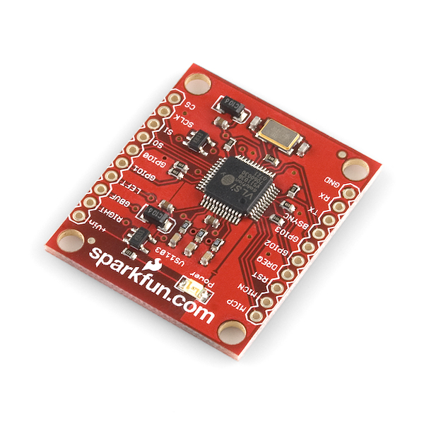
The VS1103b is a single-chip MIDI/ADPCM/WAV audio decoder and ADPCM encoder that can handle up to three simultaneous audio streams. It can also act as a MIDI synthesizer. General MIDI and SP-MIDI format files are played, with a maximum simultaneous polyphony of 40! This breakout board can be easily dropped into any project and can also drive 30 Ohm headphones directly.
- Separate Audio and Digital 3.3V supplies
- Onboard 12.288MHz oscillator
Comments
Looking for answers to technical questions?
We welcome your comments and suggestions below. However, if you are looking for solutions to technical questions please see our Technical Assistance page.
Customer Reviews
No reviews yet.
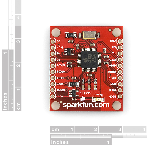
I think I've figured out what may be a slight design flaw in this breakout board - I think DVDD should be exposed as a pin on the breakout board, which would make tying a signal to the GPIO pins much easier. To work around this, I've carefully soldered a wire to the via coming off of pin 32 (TEST on the VS1103, which is normally connected to the IOPWR, aka DVDD signal) onto my protoboard to act as a 3.3V rail...
Agreed: what the datasheet calls IOVDD (pins 6, 14, 19, and 32; also the other side of the RX resistor R9) should be separate, not shorted to what the datasheet calls CVDD (pins 5, 7, 24, 31). IOVDD wants to be a 3.3V supply, although you could have a cuttable trace shorting it to CVDD if you wanted to be fancy. IOVDD wants its own pad. CVDD is an awkward 2.7V supply, you don't need to expose it on a pad, the VCC pad is fine for that.
In the data sheet it says not to exceed 3.6 volts. That is understandable for its size. Most chips that size cant exceed that anyway but how can it drive 30 ohms load ear phones? With the voltage given?
I looking to retrofit an old organ, like the chipophone guy. Is this board a good choice?
VLSI Solutions has a great doc to make a real-time midi module out of this, including the MIDI interface to connect it to at:
http://www.vlsi.fi/fileadmin/software/VS10XX/rtmidi09.zip
is there any example code for this chip?
thanks :)
If the board is set up in RT-MIDI mode as a GM synthesizer, is it still possible to use the mic/line audio input and mix that with the GM sounds? It's not immediately clear from the datasheet.
Thanks for your time.
I've used it. It works no problem. Just wire it up as per manufacturers documentation to work in RT MIDI mode.<br />
You may need to interface your keyboard midi output over an opto coupler. It performs well compared to 2 other GM midi synths I happen to have. I'd recommend it
I'm interested in doing the same thing with the MIDI input.
I have tried contacting the manufacturer of the chip to get a sample of the sounds on the chip, but no luck.
If it were to sound decent I would strongly consider buying and giving it a shot....
Has anybody managed to get this breakout board working as a midi synth?
Hi,
I have some question on this breakout board:
Is VCC 5 volt?
If yes how i have to pull up GPIO ?
Have i to carry out DVDD for this pull up or can i power the breakout board with 3.3Volt ?( regulators on board have a low dropout voltage ).
Can anybody help me?
regards
Vcc could be 5V or so (exact value's not important, it's fed directly to a voltage regulator). HOWEVER all digital logic on the board is at 3.3V and you can't give it more voltage than that. That means you should probably drive this board from something like a 3.3V arduino, using the same "raw" voltage source (something greater than 3.3V) for both.
You should not power the board with 3.3V -- in this case the actual IOVdd would be (3.3V - V_dropout) for whatever the dropout voltage of the regulator is, and your digital inputs must not be more than 0.3V higher than than (unknown) voltage. That would make properly interfacing with the board very difficult (which is one reason why sparkfun should break out the IOVDD signal on this breakout board; see above).