- Home
- Product Categories
- Infrared
- Infrared Proximity Sensor Long Range - Sharp GP2Y0A02YK0F

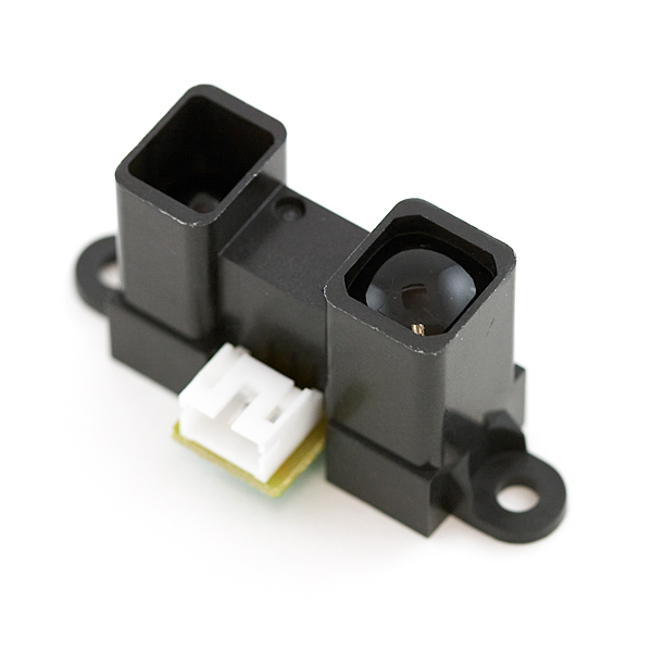
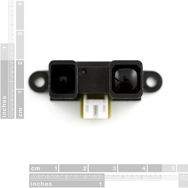
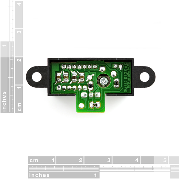
Infrared Proximity Sensor Long Range - Sharp GP2Y0A02YK0F
Infrared proximity sensor made by Sharp. Part # GP2Y0A02YK0F has an analog output that varies from 2.8V at 15cm to 0.4V at 150cm with a supply voltage between 4.5 and 5.5VDC. The sensor has a Japanese Solderless Terminal (JST) Connector. We recommend purchasing the related pigtail below or soldering wires directly to the back of the module.
This sensor is great for sensing objects up to 5 feet away!
Infrared Proximity Sensor Long Range - Sharp GP2Y0A02YK0F Product Help and Resources
Resources & Going Further
For more project ideas about the IR Sensor? Check out the following blog posts::
IR Interference
If you are trying to use a TV remote/IR remote control, the sensor can have issues if the control is shining directly at the IR sensor.
Core Skill: Programming
If a board needs code or communicates somehow, you're going to need to know how to program or interface with it. The programming skill is all about communication and code.
Skill Level: Rookie - You will need a better fundamental understand of what code is, and how it works. You will be using beginner-level software and development tools like Arduino. You will be dealing directly with code, but numerous examples and libraries are available. Sensors or shields will communicate with serial or TTL.
See all skill levels
Core Skill: Electrical Prototyping
If it requires power, you need to know how much, what all the pins do, and how to hook it up. You may need to reference datasheets, schematics, and know the ins and outs of electronics.
Skill Level: Noob - You don't need to reference a datasheet, but you will need to know basic power requirements.
See all skill levels
Comments
Looking for answers to technical questions?
We welcome your comments and suggestions below. However, if you are looking for solutions to technical questions please see our Technical Assistance page.
Customer Reviews
4.5 out of 5
Based on 2 ratings:
This Sensor is Working Quite Well
The analog signal from this sensor is working quite well with my Arduino. I use this sensor to indicate when I am at my desk. The desk is positioned such that my wife can't see me sitting there. The Arduino activates a "Christmas" star ornament positioned on the top of a hutch located on the desk. This sensor is replacing an incandescent thru beam sensor that has a history of burned out bulbs due to heat. This sensor has great range and was easy to setup.
Good Sensor
This sensor is really good for the range. The only thing I wish was different is that it had a closer range that still worked well. I'm not sure what would be involved in that, but it's a good IR sensor with good readings.
I have this sensor. It's nice and does indeed have a pretty good range of several feet (I've reliably gotten 3-4 ft). There are 2 caveats. At short distances (<4-5 inches), the output goes low, and then when it gets within range, it goes high....then it gradually decreases as the distance increases. This means that there is a sort of discontinuity between 3-5inches and 5+ inches.
The second issue is that the values greatly based on the object in front and angle (ideally you need a reflective hard white surface facing straight-on). This just makes it a little hard to calibrate for some applications.
Overall, MUCH better than the ultrasonic ping sensors, and way better than trying to build your own IR/Phototransistor pair.
Hey..the project I am working on is a Posture Correction Chair...For this we have demarcated certain points of the spine that needs to be touching the chair body in order to maintain a correct and healthy posture. I wanted suggestions for sensors that could be used to calculate the distance of the chair occupant and the vertical chair body.. Suggestions do let me know..:)
can someone help me? i am looking for a sensor that can detect a moving vehicle in road.... the sensor should only detect vehicle and no other object. is this Infrared Proximity Sensor only detects metal? Thank you for your response :)
Using this sensor, an Arduino Uno and Python 2.5 for data processing I made a single pixel camera. The sensor is attached to a servo rig allowing incremental rotation along X and Y axis. Python then takes the distance values and servo rotation coordinates, converts them to luminance and constructs an image pixel by pixel:
Here's a test scan (link updated):
http://imgur.com/a/muMiX
Image on the left is taken with a web camera and the image on the right is scanned with this Sharp Sensor (over the course of about 5 minutes). Used a single 0.1uF capacitor for signal filtering.
The noise in the image comes primarily from cheap wobbly servos.
Arduino was programmed to respond to serial commands. Receiving number followed by "x" would adjust the horizontal servo. Number followed by "y" adjusted height and "d" performed an read of the depth value and returned a digit via serial port. I don't remember where I put the sketch. It's been years. I did find the Python sketch though:
import sys import os import serial import math from PIL import Image
def clamp(lowvalue, highvalue, driver): if driver < lowvalue: driver = lowvalue elif driver > highvalue: driver = highvalue return driver
ser = serial.Serial(port='COM33', baudrate=19200, parity=serial.PARITY_NONE, stopbits=serial.STOPBITS_ONE, bytesize=serial.EIGHTBITS)
imageWidth=1581 imageHeight=791 delay = 0
scan = Image.new("RGB", (imageWidth, imageHeight))
xPos = 820 yPos = 1215 rVal = 0 gVal = 0 bVal = 0
time.sleep(2) ser.write(str(yPos) + 'y') time.sleep(delay)
while yPos < 2005:
while xPos < 2400: ser.write(str(xPos) + 'x') ser.write('d') dVal = int(ser.readline())/4 scan.putpixel((xPos - 820,yPos - 1215), (dVal, dVal, dVal)) xPos += 1 time.sleep(delay)
while xPos > 820: ser.write(str(xPos) + 'x') ser.write('d') dVal = int(ser.readline())/4 scan.putpixel((xPos - 820,yPos - 1215), (dVal, dVal, dVal)) xPos -= 1 time.sleep(delay)
ser.write(str(yPos) + 'y') time.sleep(delay) yPos += 1
scan.save("c:/scan_01.tga", "TGA")
ser.close()
Thats a cool project! Could you explain how you converted the values into an image also ur email id
I completely agree that the project is really cool, and Jade's result is awesome. Kudos!
I'm going to venture a guess, but I could be wrong: closer objects (read "pixels") appear whiter, and more distant objects appear darker (and possibly smaller). You can use pretty basic trigonometry to get the x,y position of a pixel based on the angle of the servos and the distance measured.
I've actually been working on a similar project, except my sensor is mounted on a multi-chassis (tank version), and sweeps only horizontally, for reasons of speed (5 minutes for a full picture isn't practical for a vehicle application).
I have multiple settings to control the resolution and speed of the sweep. That way, when the vehicle is stationary, the IR sensor can do a wide-angle slow sweep – taking a reading for every degree across a 180 degree arc; when the vehicle is moving, the IR sensor does a narrow-angle fast sweep – taking a reading every 15 degrees across a 60 degree arc.
This looked really good when I drew it in Processing. I'm faking a 3D representation (the data is only 2D) by changing not only the darkness but also the height of each individual data point based on the distance, which simulates perspective. All objects ahead of the vehicle look like walls, essentially.
My next step has been to implement iPhone remote-control using Bluetooth. The readings are currently being sent to my iPhone (using RedBearLab's BLE Shield), but I have not yet implemented the graphical representation in the app.
hi, we have similar project and have some specific question to see if you could help. Could email me back or any other way to communicate in more details? thanks! My email is motioautomation@hotmail.com
Your images no longer work. ImageShack just redirects to a page where it plays an unconvincing ad for itself. I suggest re-uploading to imgur; it's very reliable and reputable, and it has a much better user experience than I remember ever getting from ImageShack.
That's pretty cool.
Ah, just wanted to mention this since I didn't see it here. For those looking for a quick and relatively simple way to estimate the relationship between voltage output and distance. Take the readings on the graph from the datasheet or get them from your sensor (multiply the raw output readings by 5volts and divide by 1024 to get the result in volts. slightly longer but more likely to fit your sensor).
I then graphed those readings in Excel and and found the line of best fit that most accurately followed the curve between the stated operating distances of 20cm to 150cm. Excel popped out the equation. See here: http://tinypic.com/r/2lddtvc/6
Thank you - this worked out very well for me!
Just to provide a summary in case that the picture gets unavailable (all credz goes to the kind sir/madam above):
Using the datasheet, we did a fourth degree approximation to get a close fitting formula to find the distance in cm from the voltage. Here is the formula we used:
Distance = 16.2537 * x^4 - 129.893 * x^3 + 382.268 * x^2 - 512.611 * x + 306.439 *Where x=Voltage read on ADC and Distance is in cm.
Do you have perhaps a second degree approximation for the inverse of the output?
My Arduino can't handle 4th degree equations at 50Hz... :(
11 months later, but a common thing to do in this case is to use a lookup table, you can even initialized such lookup tables on boot, but for this particular application, its probably easier to just code it in.
First, for high order polynomials you should factor them like so: d = 306.439 + x * ( -512.611 + x * ( 382.268 + x * (-129.893 + x * 16.2537) ) ) The original equation had (ax^4 = axxx*x) 4+3+2+1 = 10 multiplications and 4 additions/subtractions. Factored equation has 4 multiplications and 4 additions/subtractions.
Second, I don't know how you're planning on running this at 50 Hz since the expected response time, based on the datasheet, is 38.3 ms (or ~26 Hz update frequency).
I'm running 4 on the same Arduino Fio, at around 13 Hz each, but thanks for your help anyway. The factorisation trick will come in handy.
I don't, but I've used the second plot from the data sheet (output voltage vs inverse of distance), called it a straight line from 30cm to 150cm, and a different straight line from 20cm to 30cm. Then it is easy enough to come up with two equations calculating distance from voltage.
if your using the 3 wire connector then you need to wire the yellow to the analog in, the red to the 5V, and the black to GRD
hope this helps
From the datasheet:
ProTip: Do it! I tried throwing this guy on the same Vcc as an ATmega8 and the ATmega8 became completely unstable. After adding a 100μF between Vcc and gnd things were much better. My Vcc is still much less stable than without this part in there but it works...
lmao! "This is a really hard to find item! Limit 4 pieces per customer." vs. $13.45 10-99 (10% off), $11.96 100+ (20% off) i think there is a problem here as an individual may want to purchase more than 10 perhaps
its just the Sparkfun standard. Every single item on site has these cheaper priced listed under it. And the change all that for just three items..? (I am referring to the other two sharp IR sensors that Sparkfun sells)
So I have been trying to use this sensor, along with an Arduino Mega, to help control a robot and its direction (i.e. turn it around should it be about to hit a wall), and I have basically no idea what I'm doing when it comes to coding it. I have it all wired and the coding for the rest of the robot ready to receive the coding for the sensor, but how do I make the mega interpret the raw data from the sensor and turn it into a distance number? does anyone know any websites that could help me with this or any tutorials online?
Here is my calibration for the sensor in inches.
is there a detection angle for these sensors? ie. does one have to be directly in front... or will it pickup +/- 30 degrees, etc...
Thanks!
Hello Everyone, I am new to this sensor. I am aware of how distance is measured.
Can someone tell me how I can determine the angle of incidence ?
thanks
Great rangefinder with a solid 5-foot range. Range values may vary for different colored surfaces, making it difficult to tell the difference between a close-up IR-absorbing object or a far-away IR-reflecting object. In our experience, this difference was only a few inches. I would recommend making an Excel (or equivalent) spreadsheet of experimental ADC values vs distances and using the software to create a trend line with a corresponding equation for your software to use to estimate ranges. Runs well on a regulated 5V supply with a good-sized capacitor to counteract the ripple it will cause when it pulls current.
Hi I have one question i want to do this with ultrasonic sensor. The range of detection objects is 35-200cm, how to make from distance to picture. Did you make some scale for an example 35cm it will be white and 200cm will be black? If you have some advices pls write me i am new with this and i want to learn. Thank you in advance!
Can this sensor pass through transparent or translucent material? If no, is there any alternate distance sensor that can be used with Arduino? Thanks!
Can you PLEASE sell MORE kinds of these (especially the LONGER range ones)?
Longer range ones (100 to 550cm) like this one: GP2Y0A710K0F
http://www.sharpsma.com/webfm_send/1490
anyone know when these will be back in stock??
Still not in stock?
Can anyone hazard a guess as to this thing's beam width and pattern? I'm looking to augment an ultrasonic rangefinder (EZ-1) for closer ranges (like 75cm - 150cm); i'm hoping this things beam is narrower than the EZ-1, or i can get away with constraining it with a black tube.
Infrared tends to be pretty narrow because any wide angles would cause bad data. However, it all depends on the application. Reading the datasheet suggests that you need to protect the sensor when in certain types of lighting scenarios (outside in sunlight is an example they give).
In regards to using a tube around it... It all depends on the tube. How is the tube mounted, how long is it, how big is the diameter of the tube, etc.
I have used predecessors of this sensor before, and they do pretty well, however not every sensor meets the curve outlined in the datasheet. So it is best to do calibration tests on all infrared sensors to map out the range and sensitivity.
the datasheet says nothing about beam width, but yeah, i will experiment, it's easy enough. IR LEDs vary in beam width, a lot, generally speaking. i posted cuz i was wondering if anyone else had done these sorts of experiments. no problemo here. thanks.
I've done a couple of simple tests with a 4mm square balsa wood stick at ~30cm from the sensor. I shall refer to the data sheet for orientation description - so that the emitter is to the left or right of the detector (as opposed to above or below). When the stick was oriented vertically, and passed from one side to the other, it seemed to have a 2.5 degree detection beam. When the stick was also oriented horizontally, and passed from below to above (or vice-versa), it appeared to have a 3.0 degree detection beam. I hope this helps.
'hope this helps'? lol hell yes! thanks a ton, man/ma'm! that's exactly what i needed. very, very helpful.
Hey Everyone, I am new to this type of sensor, I am using a 10kohm resistor between the pin back to my MIDItron. Does anyone know if I should connect the sensor without the 10kohm resistor? Also if anyone has any tips or hints on the codes using Max6/jitt I would greatly appreciate it. Thanks!
I am experiencing erratic behavior with my sensor ? Also it seems to be heating up alot when it is running is that normal? basically I a not getting the results I want from this page ? http://arduinomega.blogspot.com/2011/05/infrared-long-range-sensor-gift-of.html Does it may a difference that I am using arduino uno instead I would really like to get this working ? I can provide pics and wiring to help ?
thanks !!
are you using capacitors to help to balance the electronic noise? These should work fine with all arduino boards
What type of capacitor would you use for this? Would a 0.1uF (https://www.sparkfun.com/products/8375) cut it?
I used the largest cap sparkfun offered that followed the voltage regulations
Does anyone know if the infrared proximity sensors can detect distance from behind glass?
I did some tinkering with this, and from what I figured it would only work behind glass, if its pressed right against it, leaving no gap between the sensor and the glass.
The datasheet is clear it's not 15cm it's 20cm.
mine does 15 cm! thereafter the analogeRead-value gets smaller again.
can I use this one to determine a waterlevel?
so fixing it in my watertank with its beam downwards.
or does water not reflex enough to give a distance??
it works on water as well but just to be sure i'm using a pingpong ball in a tube to determine the waterlevel (see also: http://howmuchsnow.com/waterlevel/)
It sometimes works with just water. I bought an other ultrasonic (way more expensive) sensor to measure the water level. Just try it!
how to installl this on the arducopter?
Surprised at how little information this data sheet has. Even plain old LED spreadsheets usually have a Radiation pattern.
!ATTENTION!
This sensor's case has relatively low resistance (150 Ohms), be careful when mounting on other conductors.
hi guys
what is the angle range of this sensor?
thanks
regards
very nice sensor. much easier to use than a ping sensor but does not have as much range. It is perfect though for my application.
do you know how to install this sensor on the arduino mega oilpan
I did line fitting based on datasheet
For 10bit ADC such as Arduino (0-5V => 0-1023),R square = 0.9902
distance = 30431 * pow (sensorValue,-1.169)
Can someone help me with the equation to convert the reading into actual distance i.e. 975 x 1.318359375 = 1285.4mm 975 = 128.5cm
Is my thinking incorrect? or my math?
2.8V @ 15cm
0.4V @ 150cm
2.4/1024 = 0.00234375V
1500mm/1024 = 1.318359375mm
This link should help:
http://www.acroname.com/robotics/info/articles/irlinear/irlinear.html
Does anyone know how these react to different color? Say I have a white board at 2 ft and take a reading (discard first, average 4), then switch to a red, green or blue board at the same distance and take another reading the same way. Will I get the same reading both/all times or even something close?
Sounds like you've got an experiment to do!
Yup, I should get one soon then. I have the other style ones (GP2D120's), so I might try it with that tonight.
I was wondering if anyone can help me with my problem.
I bought this sensor hoping for it to track the distance my hand is away from it, which it does. However, the numbers corresponding to the distance fluctuate very quickly despite how I hold my hand still. Is this normal?
I plan to use these numbers as a way to control which sounds I play. However, if the numbers fluctuate so much it won't work.
I'm using an Arduino Uno and Max MSP for my project.
I apologize if this isn't the place to ask this question but hopefully someone here can help me. Thanks.
Other than that the sensor is plug and play =)
Make sure your power supply is clean and filter it with capacitors if necessary.
Putting a 0.1 uF ceramic capacitor on the IR sensor output may also smooth out some of the signal.
You can also smooth out the signal by averaging a set of readings in your Arduino code. Something along the lines of:
void loop()
{
sensorInput = (analogRead(sensorPin));
bufferA = bufferB;
bufferB = bufferC;
bufferC = sensorInput;
average = (bufferA + bufferB + bufferC) / 3;
delay(x);
}
That example takes a sensor reading and puts it in bufferC the first time. Second time the loop runs, that value passes to bufferB and third time to bufferA. Essentially, you get to keep the last 3 readings that you can then average to get a smooth output. By increasing the number of samples or the delay you can increase smoothing at the expense of latency.
Can we use glass case to protect this sensor from weather? Would it be ideal for car backup monitor? the ultrasonic ones arent weather proof and putting a glass case will void the range finding.
Glass case can be used for protection, provided it is flat and clear, not refracting or scattering light. Don't use plexiglass as it reduces or completely blocks the infrared light.
Regarding the main question, this would be a very bad choice for car backup monitor as it performs poorly in sunlight or under any light containing infrared spectrum. It's best suited for indoor use. Most car sensors are ultrasonic. I use this one for outdoors which has some weatherproofing http://www.sparkfun.com/products/9496. It is pricey and if you do get dirt into it, it'll be absolutely impossible to clean.
In your case I'd go with a cheap Maxsonar EZ series sensor, putting a PVC pipe extender onto it for weatherproofing. The longer the barrel, the less chances of something getting into it.
Another issue with IR sensors is that they project a dot and are only able to detect what's directly in front of them based on how well the dot is reflected. If the object is black, shiny or textured you may get a bad reading. A sonic sensor is a lot harder to fool. In addition it emits a cone-shaped sound wave, so the detection radius is much wider.
Will IR remote controller interfere with it?
Short answer - yes. Depth perception will get affected by a small amount in presence of a foreign IR light source, but the remote is very unlikely to cause a major misreading unless you shine it right into the sensor or have it against the obstacle that it's scanning.
This device projects an infrared dot and triangulates the distance based on where it sees the reflection. The dot itself is not perfectly sharp, so the triangulation result gets affected by reflective quality of the obstacle on which it lands. A dot on a white surface will appear to be slightly closer than one on a black plane. The ambient light (including sunlight) containing infrared spectrum will also increase the perceived radius of the dot.
Most IR remotes project a soft cone of light as oppose to a focused beam, so they won't cause much error in reading. A ray of sunlight, in comparison, will generate a measurement error 100x greater. The device is best suited for indoor applications with constant lighting containing the least amount of IR. To get the idea of what the sensor actually sees check out my post higher in the thread.
Hey, all these sharp proximity sensors are obselete!
I almost used them on a project.
They work reasonably well and there doesn't appear to be any single-component replacement available. Get 'em while the getting is good.
The connector is a bit strange. I unsoldered it and soldered on a few 90 degree male header pins.
Had a chance to test these out today. Managed to reliably extract about 1/3 of the maximum stated range (60cm) off a 4.5 volt power supply. Increasing the voltage to 5.5v raised the max range all the way to the stated 1.5m. Much like with sonic sensors, the power supply affects the intensity of the dot/ping and the max detection range. However the input voltage does not change the min range cutoff, so if 15cm is too much for you, go with a mid or short range Sharp sensor.
Overall, great value, fast response and negligibly low self-noise.
Would it be possible to raise the item limit to 5? The robots I build tend to have an odd number of proximity sensors for symmetrical obstacle detection. There's a central sensor and a matching number for the left and right side. 3 sensors are enough for some setups, but for anything more complex (near/far side detection) or for motion tracking 4 just isn't enough.
Last time I needed to track linear movement, I had to go with a thermopile array, just because I couldn't buy enough stand alone infrared detectors from Sparkfun.
You know, Jade, I'd be willing to bet if you explained your situation to Sparkfun, they'd let you buy the extra sensor. They're reasonable folk.
20 feet is pushing IR. I think Sharp makes one for that range. Beyond 20 feet, you'll have to rely on LASER ranging ($$$). You might also try two parallel LASER beams and a TV camera, and try analyzing the number of pixels apart the two beam dots are, but that's only theoretical and may require LASER power that could be harmful to human (and animal) eyes.
Do they make something like this that works up to 50 feet?
I hooked this up to my Arduino, but I am not getting any input voltage. How should the wires be connected?
Check the datasheet... One really fun gotcha of this component is that it needs two reads to really stabilize the data and get good information, but it will tell you the first read, meaning that if there is constant motion, or something JUST NOW stopped, your first read will be trash, and subsequent reads will actually have a basis in reality.
Re the comments on the "gotcha" - this comment threw me off a bit. I interpreted it as meaning every other read would be garbage..but actually it's really just the very first read which (for me anyway) is no big deal.
-Randy
I take that back. The input voltage seems to be random, and not related to how far an object is.
Just place a decoupling/bypass capacitor across Vcc and GND. 0.1uF will do. That will remove the noise that comes from the power supply lines.
The datasheet says to use a 10uF capacitor.
The equation I derived through measurements and am using with pretty good success is: y = 21208 * pow(x, -1.251);
y = distance in inches. x = analog reading from sensor.
The sensor works pretty good and buffering the values certainly helps with a more stable output. I'm buffering 10 values.
I forgot to buy the 3 pin JST connectors with my sensors so placed an order for a bunch of 2, 3, 4, 6, & 8 pin PH connectors (male & female) from digikey.
Sorry for multiple posts....The site is not compatible with Opera browser for posting comments.