- Home
- Product Categories
- Development Tools
- USB 32-Bit Whacker - PIC32MX460 Development Board

USB 32-Bit Whacker - PIC32MX460 Development Board
Replacement:DEV-09713. The new version of the UBW32 now uses the PIC32MX795 IC.This page is for reference only.
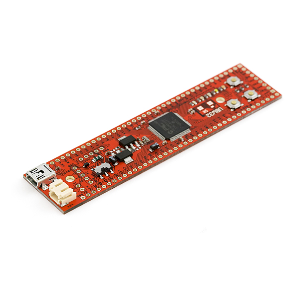
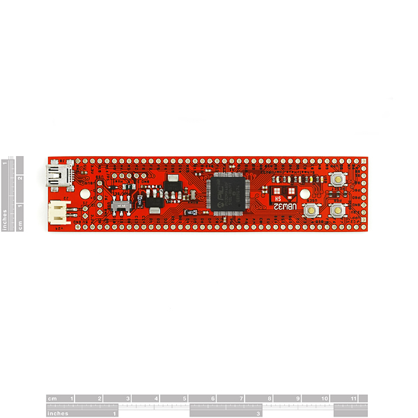
Based on the work of Brian Schmalz, the UBW32 is a small development board for the new PIC32MX460F512L 32-bit CPU from Microchip. The UBW32 is breadboard friendly and includes all the external circuitry to get the PIC32 up and running. Power can be provided over USB or from an external source. It has 3 push buttons (Reset, and 2 user-defined buttons) and 5 LEDs (Power, USB, and 3 user defined LEDs). All of the 78(!) of the PIC32's I/O pins are broken out. The board comes pre-loaded with a USB bootloader and special UBW firmware that accepts simple serial commands to control the various I/O functions.
If you have used a UBW or Arduino before and are frustrated by the lack of CPU power, lack of memory, lack of I/O pins, or lack of sophisticated software, the UBW32 is just what you are looking for! While only slightly more expensive than the 8-bit UBW, the UBW32 has significantly more I/O and CPU horsepower.
The UBW32 is also a very good stand-alone development platform for the USB PIC32 chip. It contains a simple to use USB bootloader so that you can write your own code and download it to the board without any additional programmer, tools, or software. If you need low-level debugging, you can also attach an ICD2/ICD3 or other PIC debugger.
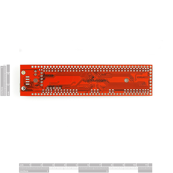
The PIC32 chip is capable of doing USB OTG, USB Mass Store, USB Virtual Com Port and USB Host roles. There is a footprint on the bottom of the board for a USB connector that will allow you to plug any USB device into the UBW32. There is a jumper that allows you to power the VBUS 5V USB wire if you program your UBW32 to be a USB Host.
**Note: **Any UBW32s bought before 11/3/2009 has the first version of the bootloader on it. This version of the bootloader causes the "BL" (bootload) command to break with the latest version of the firmware (v1.3). In order to update to the most recent version of the firmware, which fixes the problem, you'll need a hardware programmer.
**Note: **This product is a collaboration with Brian Schmalz. A portion of each sales goes back to them for product support and continued development.
- PIC32MX460F512L
- 32KBytes of RAM
- 512KBytes of Flash
- 78 usable I/O pins
- CPU runs at 80MHz
- USB Bootloader
Comments
Looking for answers to technical questions?
We welcome your comments and suggestions below. However, if you are looking for solutions to technical questions please see our Technical Assistance page.
Customer Reviews
No reviews yet.
Jordii: _Yes i feel very frustrated. I maybe will try it.. _
Yes I'm very frustrated. I will try it..
QUESTION: these seem to not be available on backorder, and on the official page of the device it says that Sparkfun will soon have a new version of the board but with a PIC32MX795. I've been holding out on buying this, already sold out, board waiting for this new revision. So Sparkfun, do you have a date for the new board? or are planning on bringing these board back on sale?
I want to buy it, but i have some cuestions.
1.- Does this version has an external crystal?
2.- If it doesn´t, does it has available pins to conect a 8mhz crystal?
3.- Can i use the optional 32.768khz crystal for the RTCC?
Thank you
The UBW32 has an external 8Mhz crystal,just like all of Microchip's development boards. The crystal is used because of the frequency accuracy requirement for USB. You can connect a 32KHz crystal to the proper pins on the UBW32, however, you may not get the cleanest signal because there will be a bit of distance between the PIC32 and the 32KHz crystal. A new version of the UBW32 (with MX795) will be available shortly that has pads on it for a 32Khz crystal right next to the PIC32.
Great product! Powering this year's controller box for West Point's Bionic Foot. Brian Schmalz's website is great and the board works beautifully. We're also using the AttoPilot current/voltage sensor and Logomatic v2, both bought off of SparkFun. The PIC32 code libraries are expanding which helps quite a bit. I put a couple YouTube videos together showing how to flash the PIC (put code on the chip) and what should happen with Brian's HelloWorld and HelloUSBWorld. Available here: http://www.youtube.com/watch?v=KOOZpQ1m0C0 and here: http://www.youtube.com/watch?v=y0d0p8xlLTI and here http://www.youtube.com/watch?v=7Jl3GNANnTQ
If using the board via "serial port emulation":
Is it limitted to be as "poll" device only?
In other words we continiousely need to "poll" the port status with the and check for changes instead of able to make use of things like "SerialDataReceivedEvent" (e.g. System.IO.Ports.SerialDataReceivedEventArgs) like we can do for normal serial-ports?
Yes, absolutely. You will be able to send data from the UBW32 to your PC over the USB serial port and use the SerialDataReceivedEvents stuff just like normal serial ports.
You do not need to poll at all (although that will work too).
The only thing that isn't supported (because it doesn't need to be) is things like baud rate and 8N1 data format, etc. This stuff is meaningless unless you actually have a USART on the other side.
any C compiler for PIC32MX460?
Yup. MPLAB C32 is free (From Microchip) and works wonderfully. It's based on GCC and is powerful. Download MPLAB and C32 from Microchip and you can build and run all of the UBW32 software projects.
any C compilers for PIC32MX460?
So I now have 2 (v2.5). I have the power switch set to USB and plug them in to the computer. The blue power light comes on but the computer doesn't recognize it as a USB device. I also tried installing the drivers separately to no avail. Could someone offer advice? I looked at the data signals on USB and saw nothing. (I've tried the devices on both a Windows 7 and XP machine).
Contact SparkFun support. There was a batch of UBW32s that went out unprogrammed. Sounds like you may have gotten one.
What would be uber cool for this is to have the new PIC32MX795 on these... The additional peripherals would be nice to play with...
Your wish may be coming true very shortly. Stay tuned . . .
The Waiting is the Hardest Part...
Any progress on the new board?
The CUI32 [1] currently under development [2] uses the PIC32MX795F512H. You can build it yourself or wait until SparkFun sells the updated version.
[1] http://www.sparkfun.com/commerce/product_info.php?products_id=9645
[2] http://code.google.com/p/cui32/source/browse/#svn/trunk/eagle/CUI32_v17
You guys did horrible job!! damn! of cuz it was my fault that i just copied design blindly....but the biggest thing which sucks is that even after those comments u did not fix the eagle schematics on ur website... and of cuz its my fault that i did just copy and didnt check thoroughly...
I've been looking at this board quite a bit, and i've got one real question, is it possible to program this board from Linux?
Yes. See http://www.paintyourdragon.com/uc/ubw32/index.html
Im going to be getting one of these, but I need to reduce the PIC's voltage down to 2v6 to allow it to talk directly to a Telit UC864 3G GSM module. Is this change just a simple recalculation of the resistor pair on the 3v3 regulator?
Yes, I believe that's all you'll need to change. Nothing else on the board depends on 3.3 other than the PIC.
The one thing to check is the USB voltage requirements. Look in the PIC32 datasheet - some other USB enabled micros I've used require special voltages in order to use the USB peripheral at voltages lower than 3.3V.
If someone succeded downloading Eagle files?
All my attempts to download UBW32_v24.zip file resulted
"It does not appear to be a valid archive" message.
Weird, i can unzip the files fine. Try to use WinRAR when unzipping the files ( http://www.rarlab.com/rar/wrar391.exe ), if you already are using WinRAR then update it. To extract the file after installing WinRAR, simply rightclick the file and choose "Exctract Files Here". Hope this helps ;)
I just uploaded the Hello World project (http://www.schmalzhaus.com/UBW32/FW/HelloWorld/) via the HIDBootloader, now i cant fin the device when i connect it to my computer (USB). How do i reset it? :(
Forgot to put this in my comment, but the hardware manager is saying: "This device cannot start. (Code 10)" in the "Device Status" box.
Sorry, my wrong. Figured out that ive bricked the circuit. I orderet the PICkit? 2 Starter Kit from Microchip, hope this will solve the problem since i can hardware program is now :]
I just bought this circuit (Have not received the circuit yet), and I'm wondering if the output pins supplies with (+) or (-), and if i have to insert (+) or (-) into the the input pins. If I'm correct, the output pins supplies with (+) and the input pins (-)? I tried to figure this out by reading the datasheet file with no luck :(. I need to know this, so i know wether i should place a transistor on the IR receiver or not :]
Thanks for any relpies :D
If I follow your question correctly, the answer is that it is configurable in software. When you setup the pin in your software you select if an output pin is configured for open drain (active low - sinks current to gnd) or not. Inputs would be high impedance and offer a software-selectable pull-up resistor. I think most microcontrollers offer similar features these days. I expect you can connect your IR receiver directly, but YMMV depending on what you have and are trying to do.
Ok, thank you very much :D
I just posted an LED Blinking program for this board written for the Hi-Tech PICC32 compiler over in the forums: http://forum.sparkfun.com/viewtopic.php?t=17769&start=0&postdays=0&postorder=asc&highlight=
I hope this helps some people get started with their own-brew code! (sorry, it doesn't use the HID uploader yet so you'll need some other way to program the board...)
Another note about these:
The LED's and switches are on Port E not Port F. This isn't noticable on the schematic linked here unless you zoom in a lot.
I wasted a fair amount of time on this so I figured it'd be worth it to point out.
I'm working on a "Hello World" blinking led example for the Hi-Tech Picc compiler now...
I pulled this thing out of the SparkFun box and I'm already impressed. It's a solid board with solid drivers and solid uploading software.
A few suggestions to SFE though:
1. Make the screen print color White! The black is hard to read...
2. Put a link in the Description to where we can get the HID uploader software! It was a bit of a search to find it...
3. Get some tutorials up for this thing! I'll try to post a few after I get my head around it a bit more...
4. Most importantly, start selling the cardboard shipping boxes you use! Those little red boxes are great temporary project boxes!
Thanks for yet another great board otherwise though!
I agree with everything you said. (Especially the red shipping boxes - I keep ALL of mine and use them to store all of my little goodies.)
I will change the silk to white in the next version. I will put up a link to the HID bootloader application. I would LOVE it if you could put up some good tutorials. (I haven't had the time.) The next version will also have pads for a 32KHz crystal, and improved routing on the back side of the board (by removing the spots for pull-up resistors, that I don't think ANYONE is using.)
When will you deliver this new version ?
It should be available shortly. Sorry for the wait.
StickOS is a lot easier to use than Mircochip's C if you're just getting your feet wet or want to do a little more than the built in firmware
Would it be straight forward to interface this unit to an encoder and LCD to totalize the count during each timebase cycle, convert the rate to engineering units, and to display on the LCD?
Yes, if you are familiar with C, you'll have no problem doing this. The UBW32 has SPI, I2C and parallel ports, so you can easily talk to the LCD if it uses one of those interfaces. Reading an encoder is very easy too.
You could start with the UBW32 firmware, or write your own from scratch.
I think I may try this instead of the LPC.
What devel tools are there?
I see Microchip has a c compiler but it looks like it wouldbe handicapped unless you pay for it.
Any suggestions for a free devel env for these?
The development tools I used for the UBW32 project are MPLAB and C32, both from Microchip. I used the free version of C32 (MPLAB is always free) and it works just great. There are some small optimizations that you don't get with the $$$ version, but it makes no difference because we have tons of Flash and RAM on this beast. I strongly suggest you try the free C32 version - I've never used anything else because I've never felt held back by C32 in any way.
Having said that, StickOS is far easier to start with (especially if you don't know C) and is a cool way to write code for the UBW32.
I would like to use the UBW32 as a replacement for using my parallel port for I/O from my computer. What is the fastest speed at which one of the I/O pins can have a single bit of data output to it, and what is the fastest speed at which one of the I/O pins can have a single bit of data read from it? Also, what is the latency in reading/outputting a single bit from/to a pin?
Any help is greatly appreciated.
Thanks.
I've done a little bit of testing (see http://forum.sparkfun.com/viewtopic.php?t=17247 for more information and code) and it looks like you can get 12,000 'commands' (setting a bit high or low) out to the UBW32 per second. So that gives around 100uS/bit toggle.
The UBW32 can toggle an I/O pin at 40MHz, and it can read an I/O pin at 40MHz. You can achieve those speeds with custom firmware. The stock firmware for the UBW32 is not able to read or write anywhere near that fast, although I have not measured it. I will do so, as that is an important metric. Note that none of the code so far has been optimized with this in mind - it is really meant to be more of an example firmware that you can then take and build your own functions into.
As far as how fast things can be transferred to/from the PC, it should be possible (with the right firmware) to get close to 400KBytes/s or higher, but again I need to measure that and post it.
Actually, this is simply a confusion - the UBW32 on my UBW32 website (schmalzhaus.com/UBW32) has a BOM and schematic that use LM317s. However, when SparkFun decided to take my design and build them to sell, they changed to FAN1117As. See their datasheet here : http://www.sparkfun.com/datasheets/Components/FAN1117A.pdf
You'll see that they did the right thing in the schematic and followed the datasheet for the part.
This is one of the dangers of not putting real part numbers in the schematic PDF.
Rest assured, the UBW32 works just fine - the 5V rail generates very nice clean 5V with the regulators as built.
I will try to get future versions of the schematic cleaned up and have part numbers added so that the two designs can be in sync once again.
Sorry for the confusion-
*Brian
There's one big power supply blunder in the Eagle Schematic file posted for USB Bit whacker.
In both 5V and 3.3V voltage regulators (LM317), the resistor from the 'OUT' pin is connected in series with the resistor on the 'ADJ' pin which is WRONG. The resistor from the 'OUT' pin should be connected directly to the 'ADJ' pin. In the 5V case, the IC is outputting 1.2V.
Kindly modify the Eagle schematic before someone damages his own circuit in trying to copy from the schematic.
Ahh, now I see what you mean. There are two different schematics - one on my site and one on SparkFun's. Mine is wrong. It uses LM317s, but has the resistors connected incorrectly.
Luckily, none of those boards ever got built - the schematic on Spark's site is the one used for the production boards.
*Brian
I want to use it in a car with XBee modem and other things like sensors, and stuff. Can I use this board as standalone (without a PC connected to USB)?. To use it standalone: should I have to delete bootloader and then load my HEX program through ICSP (ICD2) like any other standalone MCU ??
Yes, absolutely you can. You write some code, download it using the USB bootloader, then unplug from the PC (and obviously supply power to the UBW32) and your application will run. You can write that application code to do anything you want. There's no need to remove the bootloader - it will simply pass control to your application on bootup.
I have several UBW32 in permanent installations that work exactly this way. (If you're ever here http://www.discoveryworld.org/ check out the bubble raster array exhibit.)
*Brian
hi
thanks jproach & brennen , and thanks for the link to PuTTY , i see there is more info and help on the forum here , looks like i have some reading to do ;-) , thanks again
my UBW-32 came today , and is a great little board
plug it in , point windows to the driver , download from http://www.schmalzhaus.com/UBW32/
and it installed itself on com port 5 , i use tera term pro ( free terminal program ) and it only supports com's 1 ~ 4 , so i went into device manager and switched com 5 to com 2 and after typing V into the terminal program , i was greated with "UBW32 Version 1.0" , very cool little board , thanks Sparkfun
To allow use of COM5+ in teraterm: go to teraterms install directory, open Teraterm.ini, and edit the line MaxComPort to a higher number.
It might also be worth giving PuTTY a shot, since Tera Term hasn't been actively developed in almost a decade. Docs here.
I also just noticed this fork of the original Tera Term, which might be worth looking at.
Actually not true. TeraTerm development has been restarted.
See http://logmett.com/index.php?/Products/Tera-Term.html
The new version (4.6.1) is now greatly improved over the older versions.