- Home
- Product Categories
- Sensors
- Ultrasonic Range Finder - Maxbotix LV-WR1

Ultrasonic Range Finder - Maxbotix LV-WR1
Replacement:SEN-11724. The High-Resolution version of this sensor is now available so this one is being discontinued. This page is for reference only.
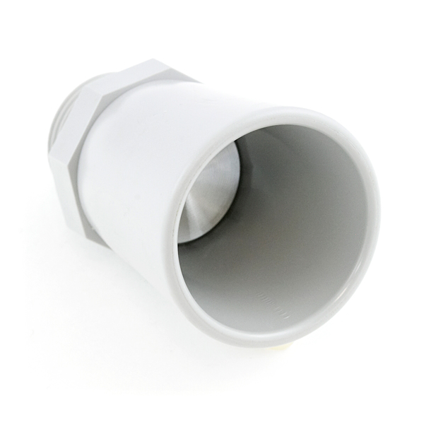
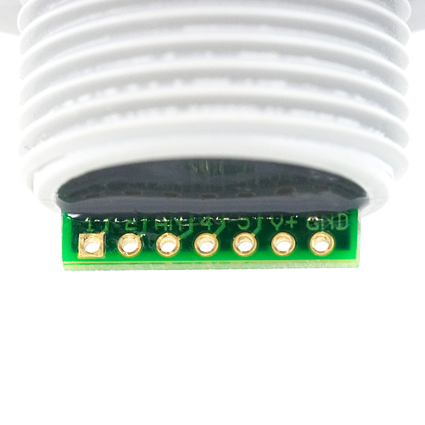
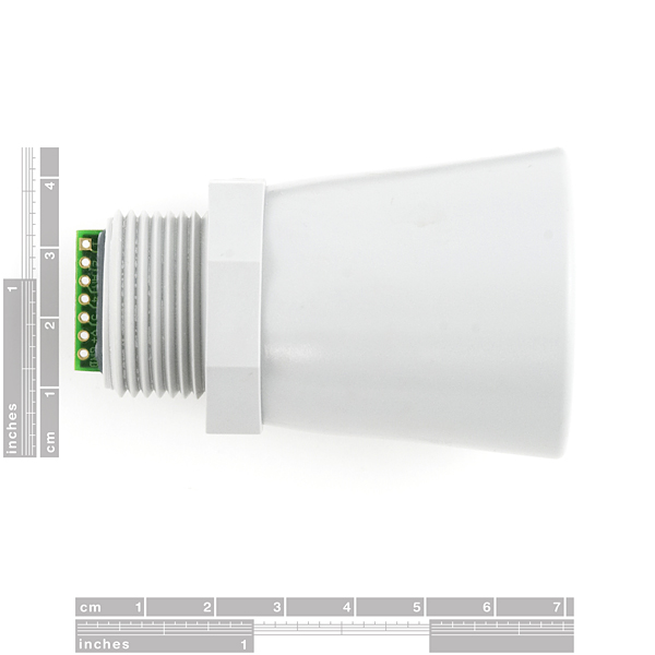
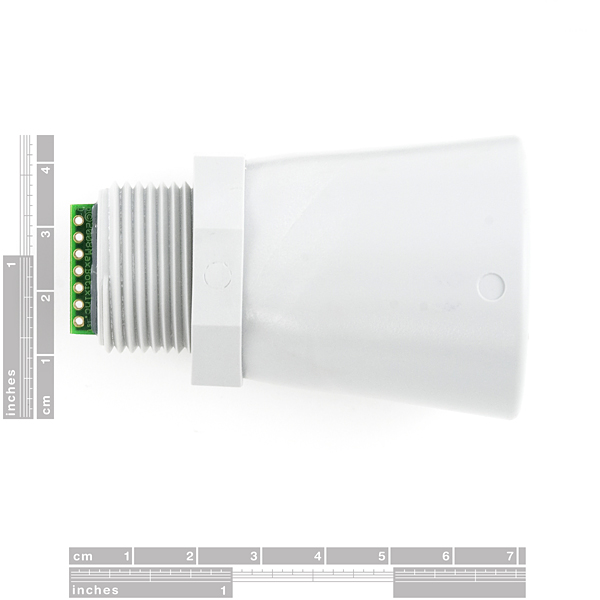
This is the new, weather resistant, field-hardened WR1 from Maxbotix. The WR1 uses a robust PVC housing, is designed to meet IP67 water intrusion, and matches standard electrical 3/4" PVC pipe fittings. We are extremely pleased with the size, quality, and ease of use of this low voltage weather-resistant range finder. The serial interface is a bit odd (it's RS232 instead of standard TTL), but the PWM and Analog interfaces will allow any micro to listen easily enough. The sensor provides very accurate readings of 0 to 254 inches (0 to 6.45m) in 1 inch increments with little or no dead zone!
Maxbotix is offering the EZ0, EZ1, EZ2, EZ3, and EZ4 with progressively narrower beam angles allowing the sensor to match the application. Please see beam width explanation below.
Control up to 10 sensors with only two pins! Checkout the Maxbotix FAQ listed below.
Detailed dimensional is found in the datasheet below.
Mounting hardware is found here.
- 42kHz Ultrasonic sensor
- Operates from 3-5.5V
- Low 2.1mA supply current
- 20Hz reading rate
- RS232 Serial Output - 9600bps
- Analog Output - (Vcc/512)/inch
- PWM Output - 147uS/inch
- Designed for outdoor applications
- Datasheet
- Beam Width Explanation
- Maxbotix FAQ
-
Checkout Mikey Sklar's flame-based trampoline, the high-lighter, using the EZ1!
Ultrasonic Range Finder - Maxbotix LV-WR1 Product Help and Resources
"RS232" Output or Inverted TTL
If the ultrasonic range finder indicates that it has an "RS232 Serial Output" and is outputting an inverting signal with the voltage level based on Vcc, you could just use an inverting circuit using a transistor to invert the signal. This is not a standard RS232 that uses +/-12V. There are a few methods of flipping this signal through hardware or software. The resources and going further will provide specific examples.
Inverting Signal w/ Hardware
Doing a quick test using a retired NPN transistor from our storefront, I was able to get it working based on the circuit using a RedBoard Programmed with Arduino. I was using an Arduino so Vcc in my circuit was 5V. Since it's basically two diodes within the transistor, you will want to use resistors to limit the current. I just used two 330Ohm resistors just like I was turning on an LED. You probably do not need to do this but the values might need to be adjusted when using it at higher speeds or if the transistor is not fully turning ON/OFF. Testing with a multimeter, it worked as expected. An input of 5V would result in 0V (logic LOW) on the output since the transistor was turning on. With an input of 0V, the transistor would not be conducting so the output would be held HIGH at 5V. Using an Arduino serial passthrough for further testing, I was able to view the ultrasonic sensor's output data without any problems.
"RS232" Output and Inverting w/ Software
Otherwise, you could be clever in writing your code to store the value and possibly apply some sort of logical NOT operation. In Arduino, there is a special feature using software serial that inverts the signal by setting a parameter to true [ "Software Serial Constructor" – https://www.arduino.cc/en/Reference/SoftwareSerialConstructor ]. There was someone in the Arduino forums that provided example code to invert the output, parse the data, and output it through the serial monitor here => [ User "Goldthing" - http://forum.arduino.cc/index.php?topic=114808.msg864009#msg864009 ].
Connecting Ultrasonic Sensor to Raspberry Pi
There is a tutorial from MaxBotix that shows you how to connect ultrasonic sensors to Raspberry Pis => [ http://www.maxbotix.com/Raspberry-Pi-with-Ultrasonic-Sensors-144/ ]. Certain ultrasonic sensors listed in the article require an inverter. If the ultrasonic range finder's output serial output is " RS232 " like the sensors listed under "Ultrasonic Sensors that Require an Inverter" , this indicates that the signal is basically an inverted output with the voltage level based on Vcc.
Therefore, you would need to follow the tutorial and use a serial inverter in order to use it with the Raspberry Pi. If you are using a Raspberry Pi a transistor, Vcc should be 3.3V since the Pi uses a 3.3V system.
Resources and Going Further
Comments
Looking for answers to technical questions?
We welcome your comments and suggestions below. However, if you are looking for solutions to technical questions please see our Technical Assistance page.
Customer Reviews
No reviews yet.
Confused here, above it's stated that there's no dead zone, but the datasheet says it's 12". Anything less than 12" reads as 12". So which is it?
Has anyone tried using this or any of the other range finders as a depth finder? I'm working on an aquatic project, and I'd love to mate a short ranged depth finder with it.
I'd be very interested to know the temperature range of this module. The datasheet does not give a temp range.
I've heard there might be problems in cold weather, but I'd like to use it outdoors.
I was wondering if anyone would know the total mass of this product with the IP67 housing? I found the mass of the sensor unit but not an overall mass. Thanks.
I like the led cube in the background of the video
The serial output is inverted TTL on the Maxbotix sensors. The datasheet for this model is no different. It states that you still need a level-shifter if you need RS232 levels.