- Home
- Button Pad Controller USB

Button Pad Controller USB
Replacement:WIG-09839. The board layout has been slightly modified in the new version to address footprint concerns. Other than that, the new board is essentially the same. This page is for reference only.
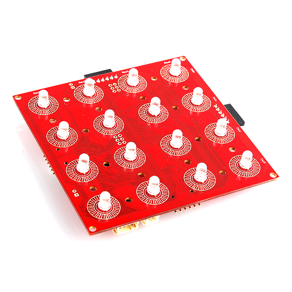
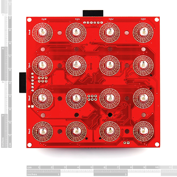
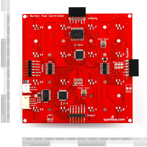
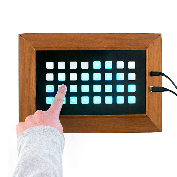
The Button Pad Controller USB was designed to control an entire multi-board system of Button Pad Controllers using an easy to use API through a USB connection. The board is 4”x4” and has 16 tri-color LEDs and 16 corresponding button pads (i.e. The button pads surround each LED). The USB Button Pad Controller is designed to communicate with up to 9 other Button Pad Controller SPI boards. The default firmware uses a 24 bit color scheme for each LED. Each board comes configured to work as a standalone unit and must be reconfigured for multiple board systems.
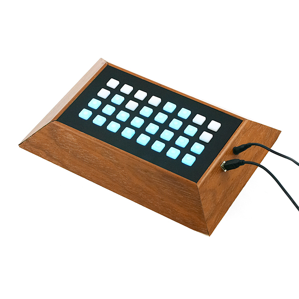
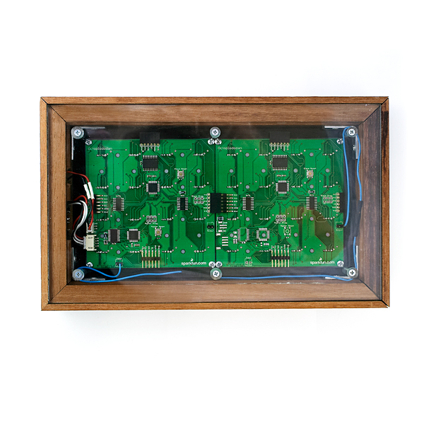
We do not sell the frames shown in the photograph. We put those together for our own use as a demonstration of what two units (USB unit and a SPI unit) look like, boxed up together.
Unit comes fully assembled and tested as shown. Unit does not include top button pad (listed below).
Note: We're using new RGB LEDs which have the blue and green pins swapped. When setting the LED color, you'll need to swap the blue and green values in the command structure. Visually, nothing on the board has changed.
Files:
Comments
Looking for answers to technical questions?
We welcome your comments and suggestions below. However, if you are looking for solutions to technical questions please see our Technical Assistance page.
Customer Reviews
No reviews yet.
is there going to be a cable to usb connector made available or will you have to make your own?
It's coming soon...
I have the board connected to a power supply and computer and I'm able to send commands and control the colors of the LEDs. No matter what I do though, I always get the return code of $00. I can hold done buttons, press buttons, but always get a $00 when I ask the status of the buttons (by sending $02). Does anyone know the secret?
Thanks
I'm getting the same exact result. No button presses are ever returned, but I can command the LEDs just fine. I have no idea why.
Hey man I'm really stuck at getting up and running with the 4x4 LED matrix. I've been able to connect the matrix via a USB to JST cable I made but I can't figure out how to get the programming interface up and running and how to program the the darn thing. Any help you could offer would be much appreciated, thanks!
OK. I admit. I'm blind - it's clearly written in the user guide: 'If you are only using the Button Pad Controller USB in a 1 board configuration you'll simply need to connect a wire from the ?Output? pin to the ?Input? pin'. Done that and it returns which buttons are pressed.
The same with my buttonpad. I can set the colors of the leds but what I get back is always $00. Even after sending 0x02. Is it possible the firmware is invalid or I am missing something?
bought the usb button pad,3 additional SPIs to go with it and an arduino usb.Can anyone help a new with a tutorial or a step by step guide how to get this all to come together for an arduinome?
So can you order the button PCB and some LED's and hook this up to one of those or will it need to be another one of these or the SPI version only that will hook up to it?
We just released a great firmware that turns the SPI version alone into a 10 track drum-sequencer with several neat features. Not sure if it would work with this version too.
http://www.youtube.com/watch?v=G3KBr0tJkug
https://github.com/Beat707/Beat707-LE
How hard would it be to make this into a Super Simon?
Does it need other cables etc. to work with a laptop?
hey sparkfun,<br />
<br />
this board doesn't have enough holes in it! COM-08746, COM-08747, and COM-07835 all have four holes per segment for a total of 16 holes, but this part only appears to have the four perimeter holes. <br />
<br />
COM-08033 appears to have the correct number of holes, though. maybe it's time to update the eagle file for this part? :) (you're almost out of stock anyway. :) )<br />
<br />
The schematic for this references an ATmega48, but on my board I have an ATmega168 20AU. Is there an updated schematic available?
Would it be possible to patch into the uC's RX/TX pins directly, bypassing the FT245RL and making this product easily useful with a generic microcontroller that does not implement USB host mode?
I realize there is an SPI version, but I have sunk $50 into this USB version and would still like to use it with a uC (without implementing USB host mode).
From the ATmega168 data sheet: "The ATmega48, ATmega88 and ATmega168 differ only in memory sizes, boot loader support, and interrupt vector sizes." So nevermind about the schematic.
I guess I might be able to speak FT245RL (parallel FIFO) to the board from my uC. A PITA, but at least it's easier than writing a usb host driver.
http://www.sparkfun.com/datasheets/Widgets/ButtonPadController-USB_v24.pdf
^^^^^^^ Just to mention, on the 3rd page of the schematic, it says that the power supply is 5v as "38Amps", I'm guessing that is a Typo?
It very well could be a typo. Of course you can use a 5V 38A supply just fine ;-) Too much current is never really an issue.
Why are the reset fuses blown? That makes it damn near impossible to make changes to the firmware.
(to follow up). Specifically, I have this wired up as described in these comments, but my computer doesn't see it.
ls /dev/tty.*
in Terminal gives me "/dev/tty.Bluetooth-Modem /dev/tty.Bluetooth-PDA-Sync" only.
Anyone?
It seems like the documentation for this might need upgrading. Lots of references abound to the "easy to use API" but really no pointers on how to get this thing going. I've been hitting a wall with it and not really sure if I'm missing something obvious or have soldered wrong... Anyone know of a step-by-step out there?
What's the COM settings guys? Baud rate, parity, etc? I've connected everything using any info I could find but can't get this thing to do anything. Whatever command I send (at any baud rate), I receive back (hex): 24 30 30 0A 0D
Can't figure this sucker out. Any help on how to get started will be appreciated.
This board uses a USB interface with one of those FTDI USB chips (like how an Arduino does USB), so when you plug it into your computer (after making your own cable or soldering the 4-pin JST connector to a female USB socket), the computer uses the FTDI driver to present your OS with a serial port. On my XP system it shows up as COM33. You can set the baud rate for this port via the Windows XP Device Manager -- right-click the port and choose "Properties." Mine was set to 9600 8-N-1 by default.
Does anyone know if it's possible to speak serial directly to this board without going through the FTDI USB chip?
I've got the cable connected and running, there's a little start up program that lights the whole matrix in each of the three colours. I've no idea what to do from here, somebody please advise how I can start using/programming this thing! I'm using one of these for a step sequencer as a university project if, as I NooB I need help to get up and running with this thing.
what baud rate and such is one supposed to connect to this thing at?
Hey Anyone know How Many buttons can be PRESSED AT ONCE
on this rgb button controller and have the data show up over the usb port?
Most I seem to get is @ 6. any thoughts?
best -teflon
Hey Any one got an answer for the above question?
best teflon
How are people powering these boards? Can it be done with just sparkfun parts?
oops, poorly worded. What I was really asking: what kind of power supply would be needed if four or more boards are chained together (1 USB and 3+ SPI)?
You can use one of these:
http://www.sparkfun.com/commerce/product_info.php?products_id=8734
with one of these:
http://www.sparkfun.com/commerce/product_info.php?products_id=8269
Now, let me give a little disclaimer; the worst case scenario for the current draw of each board is 290 mA. This occurs when you display 'white' on every LED. If you did this on all 4 of your boards then the power supply would fail as it's only rated to 1 Amp. But if you can avoid this situation you'll be fine powering it with this configuration.
33Warlord: _
With the board oriented with the LEDs down, and the ICs facing up, turn it so that the USB JST connector is on the left side
The pins (from top to bottom) are:
USB Data -
Vcc
Gnd
USB Data +
I soldered the cut Xbee header to a small board, then connected wired from that to a normal USB connector. It's working great!_
I have made my own USB cable connecting to the JST just like you have. When i power the board, it flashes a few colors, then keeps the bottom left LED lit. I have the board set up for single board mode with the input wire going into the same board's output. My computer cannot see this device. I have downloaded the VCP and D2XX virtual com port drivers. "ls /dev" in my terminal does not show the the tty.usbserial port. How are you communicating with this board?
my problem exactly. Did you get this figured out?
Has anyone figured out how to wire a USB cable to the JST connector on the board?
I'm still waiting for the cable so I can use this.
Guys, please release this or document how to connect a USB connector to this JST connector! These boards are useless if we can't communicate to them to set them up.
I guess I posted too quick, as I just figured out the JST pinouts. (Despite what the users guide says, the pin-out is NOT "indicated on the PCB".)
With the board oriented with the LEDs down, and the ICs facing up, turn it so that the USB JST connector is on the left side
The pins (from top to bottom) are:
USB Data -
Vcc
Gnd
USB Data +
I also discovered that a 2mm female header cut down to 4 sockets, fits perfectly into the JST connector. Xbee sockets (female headers) work perfectly for this! (http://www.sparkfun.com/commerce/product_info.php?products_id=8272)
I soldered the cut Xbee header to a small board, then connected wired from that to a normal USB connector. It's working great!
Where is that USB cable? Can i get it anywhere else?
Is there a part # or has anyone found the matching 4 pin Connector for this button pad..? Because it's not sold here yet.. I want to fashion my own 4pin JST 2 usb unless sparkfun :) starts to carry one.. within the next week
Is there an ETA on the usb cable for the board and is anyone writing a serial proxy that runs under Linux?
I notice there the link to the user guide isn't active. Is there an ETA?
Yes, it should be posted on Monday; sorry for the delay.
Well, it's only "plug and play" with the SPI version of the board, and I think that's what you're talking about. If you wanted you could probably hack the firmware of the USB controller, add some hardware to the button PCB, and then get it to work. But that was kind of the point of creating the SPI board, so...