- Home
- SparkFun Programmable Oscillator Breakout - DS1077 (16.2kHz-133MHz)

SparkFun Programmable Oscillator Breakout - DS1077 (16.2kHz-133MHz)
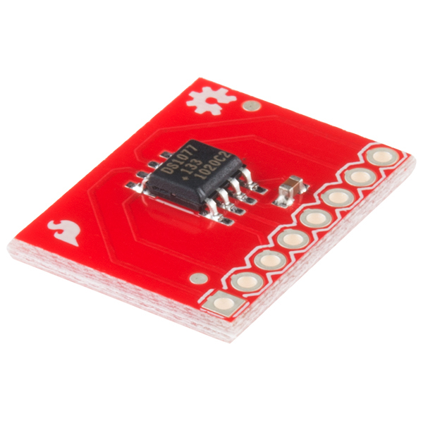
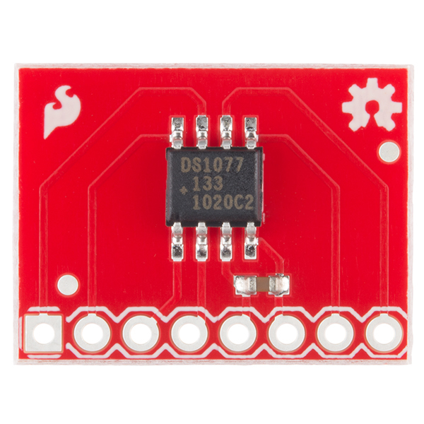
This is a breakout board for the DS1077 is a dual-output, programmable, oscillator. Contains a filter capacitor and all 8 pins broken out to a 0.1" header.
The DS1077 can be used as a processor-controlled frequency synthesizer or as a standalone oscillator. The two synchronous output operating frequencies are user-adjustable in submultiples of the master frequency through the use of two on-chip programmable prescalers and a divider. The specific output frequencies chosen are stored in non-volatile (EEPROM) memory. The DS1077 defaults to these values upon power-up.
The DS1077 features a 2-wire serial interface that allows in-circuit on-the-fly programming of the programmable prescalers (P0 & P1) and divider (N) with the desired values being stored in NV (EEPROM) memory. Design changes can be accommodated in-circuit on-the-fly by simply programming different values into the device (or reprogramming previously programmed devices). Alternatively, for fixed frequency applications, previously programmed devices can be used and no connection to the serial interface is required.
- Processor-controlled or standalone solidstate oscillator
- Frequency changes on-the-fly
- Dual low-jitter, synchronous fixed frequency outputs
- 2-wire serial interface (I2C)
- Frequency outputs 16.2kHz to 133MHz
- ±0.5% variation over temp (+25°C to +70°C)
- ±0.5% initial tolerance
- Nonvolatile (NV) setting storage
- Single 5V supply
- No external component
- Power-down mod
- Synchronous output gatin
- Datasheet (DS1077)
- Schematic
- Maxim Application Notes
- Example C Code (zip)
- GitHub (Design Files)
SparkFun Programmable Oscillator Breakout - DS1077 (16.2kHz-133MHz) Product Help and Resources
Core Skill: Soldering
This skill defines how difficult the soldering is on a particular product. It might be a couple simple solder joints, or require special reflow tools.
Skill Level: Noob - Some basic soldering is required, but it is limited to a just a few pins, basic through-hole soldering, and couple (if any) polarized components. A basic soldering iron is all you should need.
See all skill levels
Core Skill: Electrical Prototyping
If it requires power, you need to know how much, what all the pins do, and how to hook it up. You may need to reference datasheets, schematics, and know the ins and outs of electronics.
Skill Level: Rookie - You may be required to know a bit more about the component, such as orientation, or how to hook it up, in addition to power requirements. You will need to understand polarized components.
See all skill levels
Comments
Looking for answers to technical questions?
We welcome your comments and suggestions below. However, if you are looking for solutions to technical questions please see our Technical Assistance page.
Customer Reviews
No reviews yet.
Few tips:
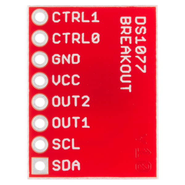
- Don't leave the CTRL0 and CTRL1 floating or it'll freak out. Both should be grounded for testing with the default settings.
- As already mentioned before, "OUT2" on the board is really an OUT0 (the one without a divider; you probably want to use the OUT1).
- Be careful about the high frequency interference/crosstalks in long lines. I've wired mine via I2C to the Bus Pirate with the output additionally wired to BP's AUX connector to be able to verify the actual frequencies while I was playing with it. It took me half a night to figure out why "suddenly" the I2C module freaked out and stopped responding to any communication attempt. Turned out the high frequency TTL-level signal in the ~15cm long ribbon cable totally jammed the I2C transmission. It was enough to crank up the frequency to anything north of 1MHz to completely FUBAR any I2C communication attempt in my case.
Before you choose this for a VFO, compute the frequencies it can generate and see if they match the ones you want.
Here are the ones I calculated from 7MHz up: 7.018 7.407 7.843 8.333 8.889 9.524 10.256 11.111 12.121 13.333 14.815 16.667 19.048 22.222 26.667 33.333 44.444 66.666 133.333
-- rec --
If anyone is interested, I just posted an mBed library for this chip (breakout board). You can download it here from the mBed website. It wraps all the functions of the chip into a nice C++ library. I included a scope output shot when the OUT1 pin is set to 32kHz.
Like Zbig stated below, be sure to ground the CTRL1 and CTRL0 pins if you're not going to use them.
If anyone wants a quick Arduino code grab that follows the Hack-a-day tutorial, I posted one here: http://jondontdoit.blogspot.ca/2012/08/using-ds1077-programmable-oscillator.html
A nice alternative to this would be the LTC6903/6904, spi/i2c addressable and much more resolution.
Slight mis-labeling on the breakout board: There is no "OUT2" signal on the DS1077. OUT2 on the board is OUT0 on the DS1077. (OUT1 is correct however)
Is this just the board or does it come with the DS1077 and the SMD capacitor too?
In case you haven't found out via some other means, it does include the IC and cap.
Most of our breakout boards come with the components described and shown on the product page.
Hack-a-day did a helpful tutorial on this item:
http://hackaday.com/2008/11/28/parts-133mhz-162khz-programmable-oscillator-ds1077/