- Home
- Product Categories
- GPS
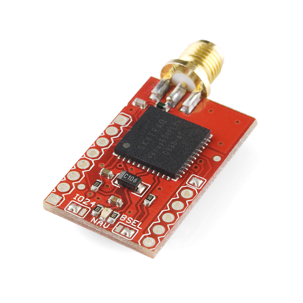
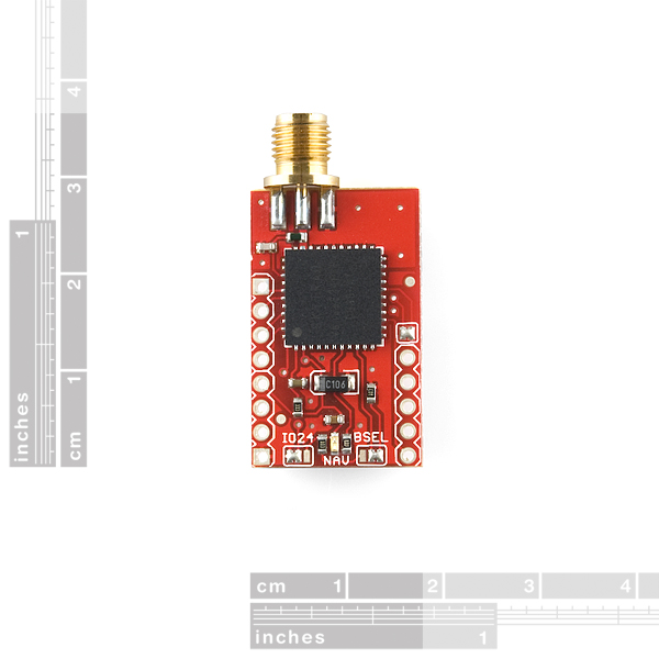
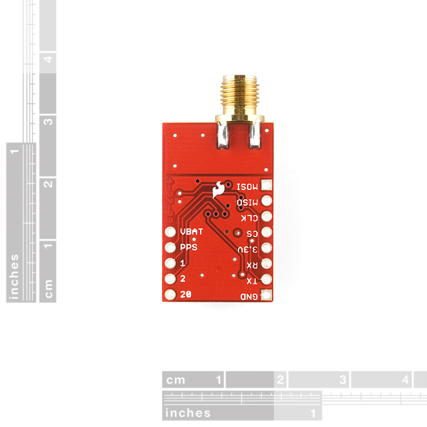
- Venus GPS with SMA Connector

Venus GPS with SMA Connector
Replacement: GPS-10921. The new version of this board is built with the Venus638FLPx-L, a more robust drop-in replacement for the Venus634LPx. This page is for reference only.
This is a development board that uses the smallest, most powerful, and most versatile GPS receiver we carry, the Venus. The module can be configured to an amazingly powerful 10Hz update rate, with 14 channel tracking! With two serial ports, UART and SPI interfaces (please see the datasheets on how to implement the SPI interface), 28mA operating current, and high sensitivity, this receiver seriously opens new doors for tracking. Module outputs the standard NMEA-0183 or SkyTraq Binary sentences at a default rate of 9600bps (adjustable to 115200bps).
The Venus634LPx has improved sensitivity, an integrated LNA (with multipath detection and suppression), built-in RTC, and integrated single power supply making it very simple to use. In addition, the module supports data logging with an external SPI Flash!
You can easily connect to the UART using our USB to Serial FT232 Breakout Board.
Check out our GPS buying guide.
Note: The GPIO pins do not serve any functions and can be left floating and ignored.
- 51 channel acquisition and 14 channel tracking
- SkyTraq based chipset
- 10Hz max update rate (1Hz default)
- Integrated LNA
- Single 2.7-3.3V supply
- 3.3V TTL UART
- Power: 28mA tracking
- Sensitivity: -161dBm
- Accuracy: <2.5m
- Hot start: 1 Seconds
- Cold Start: 29 Seconds
- Supports active or passive antennas
- Supports SBAS (WAAS, EGNOS, MSAS)
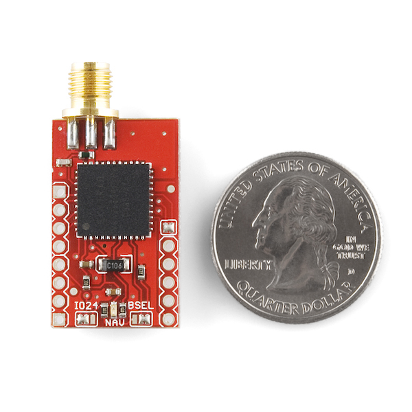
- 1.15 x 0.7 inches
- Schematic
- Eagle Files
- Venus634FLPx Dataheet
- Binary Command Set
- [GPS Viewer Software](http://www.sparkfun.com/datasheets/GPS/GPS Viewer_1124.zip)
- Datalogging Datasheet
- Design Guidelines
- Reference Layout
- Layout Guidelines
- Firmware Update
Comments
Looking for answers to technical questions?
We welcome your comments and suggestions below. However, if you are looking for solutions to technical questions please see our Technical Assistance page.
Customer Reviews
No reviews yet.
I bought this (Venus) board with the antenna and USB to serial board shown on the related products section. I also bought a spare (EM-408) cable and socket to use to make connection easier.
I'm really impressed with the GPS unit. After 10 mins of soldering connections as above I had the unit displaying in the Visualizer application. First fix was achieved in about 30secs and it hotstarts as specified in less than 1s. My next challenge is to integrate it with the Package Tracker and see if I can log it at 10Hz...
I bought this antenna and it works in my garage in Los Angeles: http://www.sparkfun.com/products/464
I also traveled to San Diego and the antenna/GPS combo worked on the entire road trip (a buddy double checked my lat/long coordinates with Google Maps as I drove). If you are working with Arduino I have some advice: TinyGPS and NewSoftSerial libraries work great with this GPS unit.
I also bought the following antenna and it doesn't work with this GPS:
http://www.sparkfun.com/products/675
Way too small to pickup a signal in my garage and when I walked around the block it still couldn't pick up GPS the signal (didn't work even immediately after successfully using my other antenna). Maybe I gave up too early. I'm going to purchase the longer version of this one and see if it works.
It won't work since the the GPS module is running at around 1.56GHz and the antenna is rated:
Specifications:
* GSM/850E : 824 to 894MHz
* GSM : 880 to 960MHz
* DCS : 1710 to 1880MHz
* PCS : 1850 to 1990MHz
So sadly the GPS falls in between GSM and DCS.
Thanks for saving me the $10. Do you know of a good, small antenna that will work with this GPS?
Hi,
I'm interessed in logging with the package tracker at 10Hz. Did you get it integrated succesfully?
Regards.
Hello Bornem,
I was wondering if you can help me on the setup of this device. I also bought the VenusGPS together with the FT232R breakout board. However, I did not realized that an antenna is required. Can you give me a link to the antenna you are using?
Thank you,
Abraham
according to the datasheet, GPIO pin 24 serves as "Search Engine Mode Selection" upon power-up. Since this pin hasn't been broken out on this board, I'm just curious whether it is tied to digital LOW or HIGH? i.e. whether the module is set to the "low power" or "enhanced accuracy" mode?
Hi,
I got informations from systraq about power modes:
"Low power mode uses 2 search engines (peak current ~50mA), enhanced acquisition mode uses 4 search engine (peak current ~70mA). Latter is faster acquiring weaker signal. Not much difference in TTFF if open sky signal 40dB or higher."
In enhanced mode, I got cold start in 20 to 40 sec (average 28s), hot start 1s, with some exceptions (one 80sec cold start and one 3sec hot start). Tested with eval board and active antenna in a quite bad environment.
I tested a second Venus that never got more than 3.3V (so its not possibly damaged). I also tested both devices about 15 miles away from the previous test. Clear skies. Results are the same. The cold start sat fix for me is anywhere between 5 minutes and 1.5 hours. 50 meter RMS in the new location.
Another person on my forum using the Venus said:
"Sometimes i'll get cold starts of seconds, or sometimes 30 minutes. On average it's around 3-5 minutes." And 15 meters RMS. He informed me that the latest Venus version now come with a VBAT jumper. He also said the power line was unstable, so I suspect a power cap was removed. Its stable on the older version, however. SF should really label version numbers . . .
The Venus is definitely not as advertised, so I wouldn't recommend it. Horrible accuracy, horrible cold start.
I just wanted to remark that I have gotten Fantastic assistance and information from SkyTraq regarding the firmware and an SDK for the chip. Their website is simple, but they are very willing to assist and responded very promptly to email's.
It has also been working wonderfully at 115200 and 8Mhz updates currently to an Arduino Mega.
Thank you SparkFun for a great little board.
And Big thank's to LittleBird Electronics (whom I purchased it from) for their prompt delivery of the product.
It would be nice if Sparkfun had a variant of this board that instead of SMA, had the Sarantel SL1300 embedded GPS antenna... It would use just about the same pad footprint as the SMA connector (maybe a little tweak).
I've been trying to get my hands on that antenna for weeks with no joy...
The module with an SMA antenna is great, simple to interface, very sensitive.
I want to buy a helical GPS antenna with SMA connection for this device. If not helical, external whip. Any sources that anyone knows of for GPS stub or whip antennas with SMA?
Just would like to add a layout suggestion. Maybe make the width of the board so that the spacing between the 2 rows of connection pads (like for .1 male headers) would be made so that this breakout board would align up with pads on another .1" spaced proto board if someone needed to place this on another circuit board. Hope I made some sense here.
Thanks
You could add this item to your "GPS Buying guide".
Also, an integrated antenna is real important. Those SMA connectors & cables are heavy.
Gidday there,
Personally, I'm glad to have an external antenna connection. Then I can place my GPS near my noisy electronics, in a cozy environment, while the antenna is closer to the sky.
Now, where can I find a nice supply of active antennas?
Joshua
Take photos at F22 so the edges don't blur. We're in a recession, man.
Skip the backup battery & use a redundant power supply for full time acquisition. It's a lot more accurate.
How is change of firmware done ? With arduino, FTDI, ???
Through the "GPS Viewer Software" linked at the top of this page. (Windows only, sorry.)
[deleted duplicate post]
The datasheet mentions putting it to sleep by disabling the power regulator. It's not entirely clear to me whether they are suggesting that I add another 3.3v regulator and disable that one or whether they are suggesting that I pull down the REG_ENA (pin 36) signal.
Does anyone know whether pulling down pin 36 will sleep the Venus638flpx? If nobody knows I will try to cut traces on my breakout board and find out.
The datasheet shows them enabling sleep mode by cutting power to the chip while leaving voltage on the VBAT line to keep the internal clock running. The datasheet shows them doing this using the enable line on an external regulator, not pin 36, unless I missed something.
I suspect that pin 36 only affects the internal 1.2V regulator, but the datasheet doesn't provide much information besides "leave it tied to VCC". Since the chip also uses 3.3V, I doubt this pin can put the chip into sleep mode, but to be sure I'd email Skytraq; they tend to be responsive to technical questions.
Thanks Mike, I agree with your assessment. I'll ask them just to make sure, since it seems like that is essentially indistinguishable from having no sleep mode at all.
Hi Doug, any resolution from Skytraq as to how to go about putting these Venus chips into sleep mode? Any help or advice would be great, thanks.
I'm in the same boat as the poster above. I have a board on order that is specifically built around this module, and I'm really hoping to not have to re-do it. I hope a new revision comes out soon with the same pinout.
Our current plan (subject to change) is to re-release this board with the new 638 chip as a drop-in replacement. At some point after that, we will relase a new board which takes advantage of the new features on the 638. The replacement board will have the same pinout, but the new board will likely have a different pinout.
is there going to be an updated board ( with the same pinout ) for the Venus638FLPx-L chip? I built a board around one of these and hoping not to have to do another board for a new module.
Thanks
See my response to sanddrag below.
I simply am unhappy with the Venus module. I've bought both the logger and standalone versions. I have tried different antennas and different settings. It pales in comparison to uBlox and Mediatek for example. It's so bad that I question how they can even still be in production. The fact that they are leads me to believe that perhaps it is the PCB / microstrip design of the board.
It would be good to do a repeat of the test in the GPS buying guide with this module. I like the size and update rate (especially the upcoming 20Hz version, wow). I would love to be proven wrong and shown what settings / ant combo works well
Can anyone please guide me on how I can interface this gps with Arduino Duemilanove. It would be of great help, thanks :)
That Design Guidelines document was a scary read. Looked like I needed to do a lot of work just to get this thing up and running.
Not so.
Plugged it into my 3.3VDC USB FTDI board and I had NMEA coming in the serial port. It's been working fine all day.
If Sparkfun does another board like this, they should consider laying it out so that it is pin compatible with the Arduino Pro Mini. Can you say, Mini-Shield?
Or at least make it pin compatible with the USB FTDI board.
Then I could heat-shrink the whole thing inline with the cable.
UPDATED FIRMWARE FILES NOW AVAILABLE
I requested an update from SkyTraq and they responded within hours.
See this post (http://forum.sparkfun.com/viewtopic.php?f=17&t=30124) for the files.
Firmware Update in documents section above is out of date. The version of firmware that was in my board when it came was:
Rom code:
SkyTraq Kernel Version 32.0.53
SkyTraq Version 51.0.20
SkyTraq Revision 2017.0.113
System code:
SkyTraq Kernel Version 1.6.1
SkyTraq Version 1.10.23
skyTraq Revision 2011.4.26
and after updating with Firmware Update above:
Rom code:
SkyTraq Kernel Version 12.96.0
SkyTraq Version 131.0.0
SkyTraq Revision 2000.96.0
System code:
SkyTraq Kernel Version 1.6 1
SkyTraq Version 1.10.23
SkyTraq Revision 2011.3.31
I looked on skytraq.com.tw but can't find any firmware to download. Anyone have a link?
Is the reason you are out of stock on this one that it is about to be phased out? If not, when do you think it will be back in stock?
EDIT: Talked to CaseyClark-Spark on IRC and he said that a new revision is underway. No other details, and no ETA.
So the draw on this board is actually something more like 84mA. I'm not sure where SparkFun (or the datasheet) are getting 28mA from. I think I must be missing something here, can anyone help me out?
Is it posible to send and resive data to this module using a PC as a Master and a uControler with the GPS as a Slave?
I want to have a host uController that has whatever function to send and receive with uart to my pc using its 3G funcions.
I've been looking at purchasing this board for a while now (primarily due to its high update rate), however, I do see on SkyTraq's website that their new module, the Venus638, supports update rates up to 20hz. The additional update rate would be very useful for our application (were looking to add GPS to the data acquisition system on our FSAE car).
Is it possible for sparkfun to make an updated board with the newer, faster chip set on it? Or, at the very least, would it be possible for sparkfun to carry the Venus638 chip set itself? I have had a hard time finding distributors for SkyTraq's products (especially the new 638), and they do not seem to respond to e-mail.
Thanks!
I second this! I'd love to get my hands on a 638 board - these chips are just impossible to fabricate myself...
What frequency antenna will I need for this device? Can someone point me to a link? Thanks ~ Derek
There are several GPS frequencies. If you open the GPS category on the left-hand side of our web site, you'll find an antennas section with compatible antennas.
Hi...I need the sketch to operate my arduino uno with the ISP Interface of this GPS module... someone could help me? thank you very much for attention... see you here ^_^
I'm sorry... for SPI interface... thanks
The SPI interface is unfortunately not general-purpose; it is specifically used by the Venus chip to log data to an SPI flash memory chip. We're bummed too.
Hi folks. a friend of mine bougth this gps module for me. he recomended to me for its speed and accuracy.
first 20 minutes, the unit worked fine (trough skytraq software).
then, the module started to send garbage. since then, i cannot make it work properly again
there's a way to reset or repair the unit?
regards;
Mauricio
It sounds like the baud rate got changed. Did you send it any commands which may have changed some settings?
Hi RobertC
i just changed sampling frecuency to 4Hz.
Mauricio,
The App (AN0003) note says
"Receivers with position rate 4 or higher needs to configure baud rate to 38400 or higher value."
Could this be your problem?
Hi,
I bought the GPS-BOB-00 718 09 133 with adapter.
With the NMEA output OK
Binary data with nothing.
Why??
Raw-data??
Thanks
Saverio Siciliano
Could you explain the role of capacitor C4?
I notice that there isn't a capacitor there in the reference design included in the datasheet, but SparkFun added one.
I confess to not understanding the purpose of the inductor either. The datasheet reference design labels it "optional" but doesn't explain why someone might choose to include or exclude it.
Has anyone succeeded in using the SPI interface to get location information? Have you also used the timing pulse output? I need both coming from a 3.3V chip.
Thanks
WW
I have this venus gps working with an arduino uno with no problems, but how would I give it commands to change baud rate, etc? I've looked at the hex codes in the spec sheet and I understand what I need to pass, I'm just not sure how to do that in my sketch. I'm using the NewSoftSerial and TinyGPS libraries, if that matters.
Thanks!
Works great indoors where no other GPS units I own (including a pricey Garmin GPS Map 496) will find any sats at all. Easy to hook up. Haven't yet tested on a moving platform.
http://cid-478828d520112340.office.live.com/self.aspx/.Public/STI%5E_01.04.48-01.10.29%5E_npse%5E_VENUS634.zip
Here's the latest firmware for the Venus 634
Hello,
I use this Venus board with a passive antenna.
On Vcc, I measured 81 mA after powering up, and 61mA after a fix. (Nav LED unsoldered).
I use power safe mode and 1 hz rate at 19200 bauds.
In the datasheet you can read "28mA operating current"!
What can I do to reduce consumption?
Thank you.
Manuel
I made a video tutorial on how to use the Venus GPS. When I made this video, it was giving me really bad reception. But thinking back to it I probably would have gotten better reception if I used a different antenna.
http://www.youtube.com/watch?v=k63vjN_DhqU
Apologies if this comes off as self-promotion, I'm posting my tutorials as I figure it'll be helpful for people . . .
I recently bought this receiver and the magnetic antenna. I was using it with a bus pirate and it had an 11 satellite fix within 10 minutes of first powering it on. It could have been faster but the first time I noticed it was after 10 minutes.
don't buy this garbage, I am on my second one, first one i chocked up as human error and ate the 50$, now months later I buy another one... I verified setup, bread boarded, ensured correct voltages and nothing...I get data but no fix after hours sitting in open crystal clear air. i see the data scrolling in the message window and might get one or two red SNR signals, "position fix unavailable"...I tried many different setups FTDI breakout and xbeee wireless same results.this antenna http://www.sparkfun.com/commerce/product_info.php?products_id=177...all i can figure is the antenna is damaged or the chip is either way i am so sick of this chip. After this and problems with a diode blocking comm on a xbee regulated explorer i am slowly losing faith in SP.
ideas? help? very welcome
...
hmm I was wrong =(
Hi, I bought one of these a while back and had the same problem of it not acquiring signal after even hours of running. However, I found that I was driving the chip through a voltage regulator that couldn't handle the current load I was applying to it and the voltage at the power pin was actually lower than expected. this caused it to spit out NMEA sentences (albeit, no data), but never acquire a signal.
the fix was to just simply put a beefier voltage regulator to the chip and everything was fine and dandy after that, got a fix really fast!
Hi, I am having the same issue as th3ri5k. Everything seems fine, but will not get a position fix, even after a few hours. I am running it through a logic converter if that matters.
Voltage is right at 3.3V. I am powering the board by 3.3V Voltage Regulator (800ma), so there should be plenty of power.
Anyone have any other suggestions? dead board?
Thanks.
Hello there,
This is a great little device.
Just wondering if anyone had any experience with the battery backup and knew what kind of current draw from VBAT I could expect if the 3v3 voltage line is cut. The Skytrak datasheet is a little quiet on the matter.
I think the Eagle files are for an older version of the device. They don't have the VBAT jumper above the VBAT pin.
Andy
Do you know when you will get this back in stock?
Hi,
Thanks for checking on this, those items are currently on top priority, and should be back in stock next week (Starting 7/19).
Thanks
Thank you
I was disappointed to find that the VENUS GPS board has a hard connection between VBAT and V3.3. Furthermore, the connection is under the chip so you can't cut the trace. This means that you can't test the warm and hot start capabilities of the chip. On the next revision of the board, please put in a jumper so that VBAT and V3.3 can be separated so you can use a backup battery for hot starts with intermittent logging.
Mark
Hello, very sorry to hear this. I think you might of some how received a very old board. We have checked our current stock and we are selling the most recent revision, v15.
Please email techsupport@sparkfun.com and they will help you get the correct board.
-Aaron
Can you use the SPI to connect this GPS to a micro?
You could, but I don't think there is much documentation on the SPI protocol, timing, etc.
The SPI interface on the Venus chip is designed to be directly connected to the SPI port of a flash chip. There are also some configuration options for the flash interface, see Datalogging Datasheet for more info.
-Aaron
Save yourself the money and do NOT buy this GPS. I ran a comparison between this model and an u-blox model. While the u-blox was keeping my robot within a street lane, this GPS was driving it into lakes. The actual accuracy I observed with WAAS correction was ~40', while the U-blox was ~4'.
Which u-blox module did you use?
GPS-09436
Sorry to hear you are having problems. We generally do not get those types of results with this board and the GPS-00177 antenna.
Feel free to email techsupport@sparkfun.com if you are not getting the results you expected or if you feel you have a defective product, we will be happy to help!
-Aaron
I recently acquired this board. I am using it with the 3.3v FTDI cable and the break away headers. Note, you must take the cable apart and re-pin it if you would like to use it.
I have found that the chip gets very hot. Has anyone else had this experience?
Thanks,
Logan
It should not get very hot. Maybe something is wrong?
Hey,
The datasheet talks about how to give an WAAS command. Does anyone know how to give a MSAS command to the GPS receiver? My experiment is in China :(
Thanks
Dan
I have been playing around with the Venus board and have developed a (Linux) Bash shell script to pull the $GPRMC message and display in a terminal window. It also checks for the (USB) port to use by reading the messages. Not elegant or pretty by a long shot, but it works...
I have put it at my server here:
http://e-zuni.com/temp/parse_gps.sh.txt
Just copy to a file. Then run in a terminal window: sh parse_gps.sh.
I would like to post it here, but half the characters would be stripped.
Just an FYI: I have the Venus connected to an active antenna (VTGPSIA-3), and powered by 3.3v from the FT232RL breakout board, and connected to a laptop USB port. This setup draws less than the max 50 mA the breakout board allows at 3.3V. The active antenna is powered through the coax cable. I built the whole thing except the antenna in a 12V auto flasher square plastic case (DOT Approved :-). Took all of two hours to package the thing. Very small: 1 inch square and 1.5 inches long. The SMA connector comes out the top and the USB connects to the bottom. Nice!
How much does this weigh?
I contacted SkyTraq several weeks ago via email, but I've gotten no response. Does anyone have a contact there for getting the new firmware?
-Scott
Hi ScottH,
I spoke with Oliver Huang from SkyTraq Technology, Inc and he was very helpful. He sent me via email the updated firmware.
Im sure you have already tried this but here is the email anyway:
Info [info@skytraq.com.tw]
If you still dont have any luck send me your email and ill forward it to you.
Hope this helps.
James
We have some updated firmware as well. Drop us a line and we'll get it to you.
-techsupport at sparkfun dot com
Oliver got back with me on my second try.
So now that I have the firmware, how do I install it? I can't find an option to do this in the SkyTraq program. I figured there would be an "upload firmware from file" option somewhere.
Thanks,
-Scott
In SkyTraq GPS Viewer to the bottom left of the scatter plot there's a download button (looks like a blue circle with an arrow pointing down).
Click the small button to the right of that to navigate to the .bin file on your computer. Then click the download button to flash the new firmware.
Download, upload, vhat is difference? :-)
I just have a question before buying this module:
When you apply power, does the GPS give each seconde some NMEA trame or does it need a request from the microcontroler to receive the NMEA trame ?
Thanks a lot !
yes unless it is told otherwise it will continusly output NMEA stanzas
Hi,
I've bought this Venus GPS from SFE. and I'm using this antenna:
http://www.sparkfun.com/commerce/product_info.php?products_id=675
But in GPS Viewer software it gives an error "Position Fix unavailable".
Is there something wrong with my antenna? or can i do it without an antenna?
Hi,
I would try using this antenna as we have found it to be the best fit; http://www.sparkfun.com/commerce/product_info.php?products_id=177
The GPS will more than likely not work without an antenna
My two boards had badly mismatched inputs--2 dB return loss. Was able to tune with 5pF capacitor in shunt. Sensitivity is poor, but works OK with active antenna when outside. Takes a very long time to first fix when signal is weak.
Also, you say 'Power: 28mA tracking'. However, I see that value in the Venus634FLPx datasheet, meaning it does not factor in the LED current.
Your board file says 330ohm, is that what you used?
If so, this device uses 38mA.
(its important to me as I only have 72mA allowed to share among multiple sensors)
In addition, your schematic says the board has a 10uF cap. But the board file and device both do not have it!
SF really dropped the ball on this one =P
So replace the LED with a diode? :)
The schematic says there is a jumper between VCC and VBAT. The board file however shows them directly connected (and no jumper in sight). Not sure why there is a VBAT pin if its connected to VCC . . . I also found two vias that don't connect to anything.
Anyway, that explains why my Venus kept heating up with 5V to VBAT. And maybe why I find cold start to take between 20 minutes and 1.5 hours, and hot start at 1 to 2 minutes.
So . . . I guess my Venus has been fried . . . why isn't this mentioned in the documentation?!?!
btw I'm using a 4.5" duck antenna outside.
The schematic shows a JP4 across the vbatt and 3.3, but I can't find any in the photographs.
The schematic doesn't show the which settings are selected for BTSEL (I assume flash, not rom) or GPIO24 (I assume enhanced not low-power? overridden by flash setting?)
I love this little board :) very easy to set up and lots of options! The gps software is excellent for getting a feel for the chip before integrating it into an mcu design.
My Venus board is back to life tonight. Don't know what went wrong before. Did not touch anything. That is some kind of good news anyways.
My Venus is dead after a month, did not touch it, was plugged but now the Venus power led lite up brightless, no signal acquisition at all. What went wrong, what do you think ?
Yeah, it happened to me too. Usually they come back to life.
ok, so if you buy this with GPS-00177, how do you power the antenna? It's not clear to me how to get power to it.
In the binary command set, there is a message (0x09) that is supposed to change the output message type between NMEA and 'Binary'.
Any idea what the 'Binary' message format is? The binary command set only describes configuration, but not GPS data.
Thanks in advance.
Joshua
Hi Joshua,
I was wondering the same thing so I contacted SkyTraq and they told me that the binary nav data messages were for a future firmware. They provided me with the updated firmware and binary command set document describing the PVT messages that can be configured to 10Hz. They have been pretty helpful.
It might be a good idea if Sparkfun add these files to this page so that SkyTraq do not get inundated with requests for the new firmware.
Hope this helps
James
I also second the vote about getting this extra information on the Sparkfun site. I've got a NEMA decoder running, but I'd rather do this via a binary protocol.
Hey James,
Thanks for the note. What are the distribution conditions on the document and firmware that you received? Any chance you could send the firmware and the datasheet to me by Electronic Ma i l?
j p l (o)) x i p h o s DOT c a
Joshua
How would this module perform with this antenna?
http://www.sparkfun.com/commerce/product_info.php?products_id=464
Thanks!
I have this GPS and the antenna you reference and the combo works great - even in my garage in Redondo Beach (Los Angeles, CA).
Data sheet says the default rate is 9600 pg 2
I just got mine and noticed the 3.3 is upside down LOL
Could you provide a footprint for it? I would like to integrate on top of my PCB design. Thanks.
Check out our footprint library, it should be in the most recent update.
http://www.opencircuits.com/SFE_Footprint_Library_Eagle
Hi,
Here it is (but not in stock ?) !
You didn't put a backup battery nor integrated antenna, it would have been nice (but maybe more expensive).
Antoine
I agree Antoine, a chip antenna would be nice and we are working very hard on seeing if we can get it to work. Although, SkyTraq has warned against using small passive GPS chip antennas due to decreased SNR. So far SkyTraq has not heard of any their customers using passive chip antennas successfully with the Venus.
Do you have a recommended antenna? Is an active necessary? It would be nice if the GPS guide had a section covering antennas. Thanks
http://www.sparkfun.com/commerce/product_info.php?products_id=464 works well :)