- Home
- Product Categories
- Sensors
- Atomic IMU 6 Degrees of Freedom - XBee Ready (Old-School)

Atomic IMU 6 Degrees of Freedom - XBee Ready (Old-School)
Replacement:SEN-09812. The new version of this board replaces the MMA7260 Accelerometer with the MMA7361. This page is for reference only.
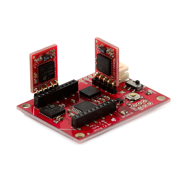
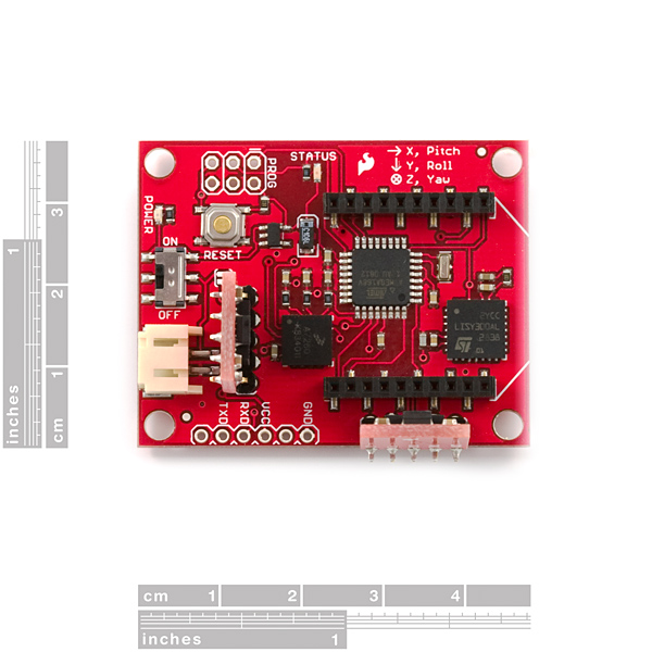
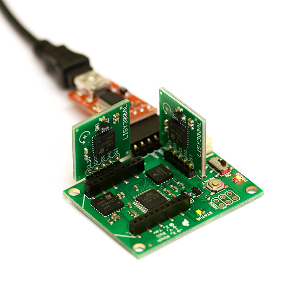
The 6DOF Atomic is a stripped-down IMU, designed to give good performance at a low price. The unit can run as a hard-wired UART interface (0-3.3V, 115200bps), or optionally with an XBee RF module, and is powered from a single LiPo (Lithium Polymer) battery. The processor is an Atmel ATMega328 running at 10MHz with 6 dedicated 10-bit ADC channels reading the sensors. Source code for the 6DOF Atomic is freely available and compiles with the free AVR GCC compiler.
The 6-DOF Atomic uses these sensors:
- 1 x Freescale MMA7260Q TM triple-axis accelerometer, settable to 1.5g, 2g, 4g or 6g sensitivity
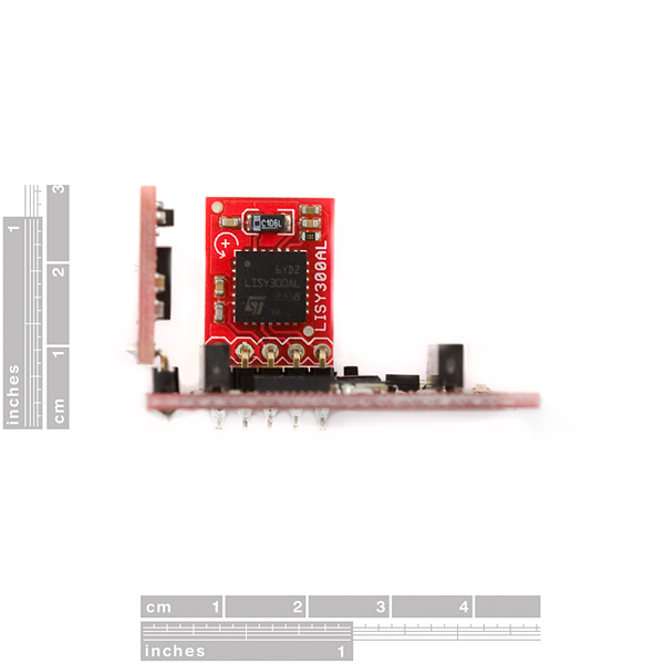
3 x ST Microelectronics LISY300AL TM single-axis, 300°/s gyros
All sensor readings are available through any terminal program in either ASCII or binary format, or with the 6DOF Atomic IMU Mixer demo application (source code also available).
Having a hard time picking an IMU? Our Accelerometer, Gyro, and IMU Buying Guide might help!
Specifications:
Input voltage: 3.4V to 10V DC
- Current consumption: 24mA (75mA with X-bee)
- Sensor bandwidth and resolution:
- LISY300AL Gyros:
- 88Hz, 0.977°/s/tick (ADC count)
- MMA7260Q Accelerometer:
- 350Hz, X and Y axes
- 150Hz, Z axis
- 0.00403g/tick @ 1.5g
- 0.00537g/tick @ 2g
- 0.0107g/tick @ 4g
- 0.0161g/tick @ 6g
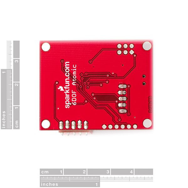
- 1.85 x 1.45 x 0.975 inches (47 x 37 x 25 mm)
Comments
Looking for answers to technical questions?
We welcome your comments and suggestions below. However, if you are looking for solutions to technical questions please see our Technical Assistance page.
Customer Reviews
No reviews yet.
Are the other I/O pins of the ATmega available?
A few pins are brought out. Check the schematic, but the RX/TX pins are, and the SPI pins are available from the PROG connector.
Hey
i've bought as well the 6DOF plc and i am wondering about the datasheet. Can somebody explain how to use it? It doesn't even start the Mixer Programm^^ saying MSCOMM32 is not registered. So I connectet the UART output port from the Atomic with an UART to RS232 adapter and afterwards the adapter to the RS232 port from my computer. But it doesnt work - damn it o_O can somebody please help ^^
Cheers
should those two giro boards be attached to the main board some other way?
for more accuracy, so the flex in the headers doesnt affect your readout. not sure how much a difference would make tho.
If you added a mere 3 or 4 servo pin headers, this unit would be a complete stand alone Autopilot / RC Receiver (with Xbee RC Transmitter). 9 pins, most of which are brought out to the programming jack.
You'd need a GPS, too, of course.
You could use one of these, of course you'd probably have to change the program a quite a bit.
Hi mates! SMT Connector for Xbee module rocks! where could I found it?
best regards.
i've adapted some code from the 9dof to work for the atomic imu.
it's still WIP, so not guarantees, though it seems to work ok
:)
https://github.com/rlrosa/uquad/wiki/ImuDisplay
the wiki is in spanish, but the code has a lot of comments in english
https://github.com/rlrosa/uquad/blob/master/src/python/imu_display.py
this is part of our final project for our university in Uruguay (three others and i)
we'll be constantly updating the wiki and adding more code.
the plan is to run the control from a beagleboard.
hope it is of use
rodrigo.
Hi guys. I've been using the atomic mixer and the xbee over serial and Im having the same problems as another member. We've both posted on the forums here: http://forum.sparkfun.com/viewtopic.php?f=14&t=28456&p=127812#p127812
Can anyone help? I cant get decent yaw values from the gyro at all
@ SFE, with the new FTDI breakout board (where you have put the 6pin female connector at the underside of the board) it is very difficult to attach it to the Atomic IMU 6dof, because then the FTDI board collides with one of the vertical gyro boards :(
Please Help!
We are having trouble accessing the configuration menu. Can someone please tell me how to get there? a step by step process wold be nice!
have a look at the source code. The 6DoF expects some characters from the PC to display the menu. If you connect the 6DoF directly to a terminal program like hyperterminal, make sure that port settings are correct (115200,8,n,1) and when connected press the "space bar" of the keyboard to display the config menu. IF you look at the source code you can easily figure this out and other commands as well. Note: this is the procedure even if you are connected to hyperterminal via Xbee
Hi, I have a 1"x 1" small PCB that does 6 degrees of freedom on batch PCB.
http://batchpcb.com/index.php/Products/51805
I2C interface
"XBee ready"--Would that be for a Series 1 or a Series 2.5?
hi
2 weeks age, i bought atomic IMU - 6 Degrees of Freedom - XBee Ready units(i am using UART communication)
i have a severe problem with this unit, i connect it to computer through serial port
it is working well when run the Atomic mixer..
but i want to get the data using matlab or hyper terminal ..
when i try to get the data using another serial program FTDI's RX light turn off..and it is disconnet..
i don't know how can i connet using hyper matlab or hyper terminal ..
also i don't even know what is the meaning of 6DOF "Atomic Setup 1.0" or "Configuration Menu" that is mentioned in
datasheet.
plz tell me the way...
thank you..
(actually i am not native so my writing skill is not good .. sorry..)
have a look at the source code. The 6DoF expects some characters from the PC to display the menu. If you connect the 6DoF directly to a terminal program like hyperterminal, make sure that port settings are correct (115200,8,n,1) and when connected press the "space bar" of the keyboard to display the config menu. IF you look at the source code you can easily figure this out and other commands as well.
Note: this is the procedure even if you are connected to hyperterminal via Xbee
I tried using one of these to build an inclinometer function some time ago but I found that a much more elegant solution for my purposes was to use a set of mechanical tilt switches. I ended up using the SQ-SEN-645B from www.signalquest.com. Maybe Sparkfun can offer these as an inexpensive solution for threshold inclinometers. I think it's a great way to do motion triggered wake up. http://signalquest.com/datasheets/SQ-SEN-6XX%20Tilt%20Sensor%20Datasheet.pdf
Hi, which lipo cell do i need to power up the board?
I've connect my 6DOF Xbee using a hyperterminal I received HEX code... but I dont understand what does that means... there's an example
Received:
0x00 0x5F 0x0F 0xBF 0xBA 0x3B 0xBF 0xA1
0x0F 0x7F 0x04 0x7F 0x0A 0x29 0x5F 0x0D
0xBF 0x5D 0x3B 0xBF 0xA1 0x0F 0x7F 0x04
0x7F 0x0A 0x29 0x5F 0x0B 0xBF 0xBA 0x37
0xBF 0xA1 0x0D 0x7F 0x82 0x2B 0x29 0x5F
0x09 0xBF 0x5D 0x3F 0xBF 0xA1 0x0F 0x7F
0x82 0x29 0x29 0x5F 0x07 0xBF 0x5D 0x3D
Received: 0xBF 0xA1 0x0B 0x7F 0x04 0x7F 0x0A 0x29
Received: 0x5F 0x05 0xBF 0xBA
Received: 0x43 0xBF 0x86 0x0D 0x7F 0x04 0x7F 0x0A 0x29
somebody help me please... where is the begging of the data frame... and where's the stop frame!! THKS!!!
How I need to connect it for using in labview???'???
Hi everybody Where are the outputs for gyro and acelerometer??? X Y Z and what i supose to receive. I need to make an application using LabView help me please!! thanks everybody!!
I would love to see the ArduIMU firmware ported to this board, or at least a DCM implementation. Has anyone attempted this or know of it being done?
hello how can i program atmega 328p on board controller with with this programmer hello how can i program atmega 328p on board controller with with this programmer AVR STK Serial Port Dongle Programmer.
the output of programmer is 10 pin but on board 6 pins are available to program...
and which one loader use to burn program
i am waiting for helpful answer...!
thank you .I have purchase already IMU 6DOF and AVR STK Serial Port Dongle Programmer
sku: PGM-00014.
the output of programmer is 10 pin but on board 6 pins are available to program...
i am waiting for helpful answer
thank you
Refer to the schematic. You must power via the JST 2 pin connector unless you close the solder bridge SJ1
I need to ask an urgent question
I use SparkFun FTDI Basic Breakout ? 5V to interface with Atomic IMU 6 Degrees of Freedom - XBee Ready and SparkFun FTDI Basic Breakout ? 5V is connected to the computer via USB connection.
The question is could the IMU have its power from the USB or do i need to use a polymer lithium battery as power source to IMU?
Is there any alternative way other than using the battery as i need IMU to be light enough and without many externals for the IMU to be suitable to Augmented Reality application.
Please answer me, waiting for the reply
Hi guys,
I?m using the 6DOF Atomic IMU. The board is hard wired connected to an RS232 port on my PC. I?m using custom made converter board with MAXIM MAX232 IC to convert from TTL to RS232. The hardware is ok.
I?m running the 6DOF Atomic Mixer application very smoothly. I set up the com port, frequency and the sensitivity of the acceleration. 6DOF Atomic IMU and the Atomic Mixer application work fine. The results are reasonable as I move the board.
Now when I connect the board to a terminal program, the data displayed (ASCII characters) have no meaning. I don?t know what I?m doing wrong here. I have tried with several terminal programs (Windows Hyper Terminal, Realterm terminal and Termite terminal) and same not reasonable data.
What I want to do: I want to see the data on the terminal and after to parse only the yaw output and use it in my application.
Please can someone help me and tell me how to get the right data on a terminal program. Maybe I should use some other terminal program.
Thanks in advance.
Cheers,
Sazdo
hello
1.tell me about atomic IMU code compile in avr studio4 give error of rprintf header not include where i can add the rprintf.c header to include and which complier are more suitable ..?
2.how i can program the controller i dont serial burner device to burn the code in atmega168 controller..?
3.tell the which xbee tx,rx module is suitable for sensor IMU data communication and how much(cost)...?
4.how much time to deliver the order..?
thank you and waiting for reply
hi;
i have a severe problem with this unit, i connect it to computer through serial port (which i am sure it is working properly) with a max232, and run the Atomic mixer; well... nothing happens. i don't even know what is the meaning of 6DOF "Atomic Setup 1.0" or "Configuration Menu" that is mentioned in datasheet.
i have seen the voltage level of Rx and TX pins of micro, they are OK, i mean, i think the serial port is good, the unit starts with 5 blinkings of status LED, and then goes to idle state.
can anybody help me?!!!!
thanks
I'm a student. I have problem and I need your help...
I hace XBee Explorer USB (WRL-08687) connected with Xb24 (1) & a Atomic IMU 6DOF, SEN-09184 connected with Xb24 (2) & XBee Explorer Serial (WRL-09111)connected with Xb24 (3).
I have X-CTU sofeware and use "Remote Configuration" to config ( Network & security, RF interface, Serial interface....). Then i use Range Test in X-CTU and try to sent data from (1) to (2). I transfer the data {that (2)received from (1)} to (3). The problem is that
+ (3) can't receive data that (1) sent
+ if i sent data from (1) to (3) everything is ok
Please help me to make it throught.
Thanks and waitting for your replay!!!
I'm a student, I have a problem and i need your help...
I hace a Atomic IMU 6DOF, SEN-09184 connected with Xb24. I don't have "serial to usb board" and i used USB wire to provide supply to SEN-09184.
+I download "Atomic Mixer" and i can't connect to comport Can i use it for tests? If can't,what should i do to test it?
Please help me to make it throught.
Thanks and waitting for your replay!!!
I have just bought two Xbee module(WRL-08687 and WRL-09111) and one Sen-09184 to set up a wireless sensor network,but I don't know how to configure to transceiver data between them that base on Zigbee (802.15.4).I'm using X-CTU solfware to do this but i haven't understand clearly yet.Can anyone help me do that problem,please?thanks a lot.
Best regard!
In the next revision, it'd be really excellent to have the SS pin broken out somewhere on it, and roll/yaw shifted down two pins to free up the i2c connectors =)
As-is, you can use the uart pins for an ss pin if you're the spi master, but a board like this would like to be the slave so you can just poll imu data, or implement a software i2c, but no way to use the internal i2c or spi as slave.
Anyways, I have some good working kalman-filtered roll & pitch code. My output code is not currently working, so it's removed from this: http://pittsburgh.benpeoples.com/code/BLP6DOF.zip
When are we going to get one of these with the new accelerometers that will make the board flat?
Does anyone know exactly how to interpret the numbers that this device outputs? Sitting level the device gives a reading of about 770 for the acceleration on the Z-axis and a reading of roughly 500 for the roll, pitch, and yaw. How many g's and how many degrees/sec are these readings?
The numbers you are seeing are raw ADC conversion results. In order to understand the output you will first need to know how to convert this number into a voltage. The general ADC conversion equation is this (you can find it on page 256 of the ATMega168 datasheet):
raw ADC value = (Vin * ADC resolution)/Vref
in this case ADC resolution is 10 bits, so 2^10 is 1024. The Vref is 3.3V, and the raw ADC value is the value the atomic is outputting. So if the z axis is 770, the actual Vin is about 2.48V. Now you need to use the MMA7260Q datasheet. On page 3, there is a table that shows the resolution and zero values for the accelerometer. At zero g the accelerometer is supposed to output about 1.65V. take this value and subtract it from the 2.48V and this gives how many volts above zero g the accelerometer is experiencing, so in this case about .83V. Now if you look at the sensitivity of the accelerometer (also on page 3) you can see that at 1.5g range the sensitivity is about 800mV which means the z axis is reporting almost exactly 1g, as it should be. You can follow the same procedure for the gyros.
You can also calibrate the accelerometer by seeing what the actual zero-g, and 1g readings are for your unit. to do this all you have to do is take a reading with z axis experiencing 1g (you have already done this), and with the z axis at zero g (to do this all you have to do is hold the atomic vertically). You can use this zero g value as your zero g reference and the difference between the 1g and 0g reading as the accelerometers actual sensitivity. This can also be done for the other accelerometer axes.
Would it be a valid approach to remove the zero-g (1.65 V) for all three axes?
How could the gravitational force be removed? Say, for a human motion analysis application?
Do we need to use angular data from the gyros to calculate the actual orientation of the sensors, and then compute the contributions of the gravitational vector to remove it from each axis?
Would you kindly give an overview of such estimates?
We are seriously stuck on this issue.
Would it be a valid approach to remove the zero-g (1.65 V) for all three axes?
-That is the idea, however the accelerometers used on this IMU are relatively cheap and thus tend to drift. The voltage bias you need to remove may drift as well.
How could the gravitational force be removed? Say, for a human motion analysis application?
Do we need to use angular data from the gyros to calculate the actual orientation of the sensors, and then compute the contributions of the gravitational vector to remove it from each axis?
-The gyros give you your angular rate, so you would have to integrate those values (after adjusting for the bias) to get your angular position. If you want to do complete 6DOF tracking (position + orientation) GOOD LUCK! It is very difficult to track position with this module, since 1) gravity is tough to subtract out once you are moving and 2) acceleration is integrated twice to get position. HUGE errors will add up after a short time
Would you kindly give an overview of such estimates?
We are seriously stuck on this issue.
-I would not recommend using the accelerometers for tracking position on any small scale, but they would work fine if you are not moving (in a particular axis) and you want to determine your gravity vector.
I believe the gyro axes are mislabeled. Pitch is about the y-axis and roll is about the x-axis. It looks like the code has is mislabeled as well. If all the channels are enabled it should be:
acc_x
acc_y
acc_z
roll
pitch
yaw
I think that you are correct. I was just messing around with the mixer program and noticed what you are talking about. I am wondering if this is easy to fix.
What is peoples opinion here, is 10 bits enough for accurate readings?
10 bits = 1024 values (0-1023) that is enough for me to have very acurate devices.
10 bits = 1024 values (0-1023) that is enough for me to have very acurate devices.
Who cares about bits? Resolution is the important thing here.
More bits = higher resolution. :P At 10-bits, the noise floor of the A/D converter is probably higher than the noise floor of the actual rate gyros... but I am too lazy to say for sure.
Would it be possible to get the Eagle files for this unit to be posted? Looks good! Cheers.
Why has the "bluetooth 6dof IMU v4" got an ARM LPC2138 of 32-bits and this one has a micro with only 8-bit CPU?
Is there much more difference implementing the kalman filter in a 8-bit micro instead of in a 32-bit micro?
You most likely will need a floating point processor. I believe that is the key difference between the two processors.
Is the bootloader of the ATMega168 installed?
Thanks
Hi!!!
I've read in your post (http://www.sparkfun.com/commerce/categories.php) that in the Atomic IMU is implemented the Kalman filter (my doctor will be grateful to you!!). But in the source code available in this web I can not find it... Is it exist?
Another question: is it possible to obtain a 6dof IMU only with gyro+acc? How is the yaw angle compensated? I thought that the magnetometer was neccesary to compensate the yaw angle (calculated by the z-gyro)
Regards!!!
A magnetometer is only necessary in the first stage of IMU navigation, finding your heading. A gps unit is used to find your location. Then by monitoring your change in heading (via gyroscope) and your change in velocity(via accelerometer) you can determine your change in location.
This module would be useful only in an application where orgin and heading aren't necessary, unless you add them yourself. An application they would be useful in would be say a model rocket. Who cares where it starts, but we want to know how far and how high it traveled and how long it took to get there.
If you have more questions email me.
I believe it just said "filter to your heart's content". I think they mean you can write in your own filters, local to the IMU or to the host which is reading it. Didn't see anything that specifically mentioned included Kalman filtering algorithms... it just linked to the wikipedia article. Implementing it is up to the user for now.