- Home
- Product Categories
- Sensors
- IMU Analog Combo Board - 5 Degrees of Freedom IDG500/ADXL335

IMU Analog Combo Board - 5 Degrees of Freedom IDG500/ADXL335
Replacement:SEN-11072. This brave warrior was laid to rest during the SparkFun Viking Funeral, but like the mighty phoenix, it has risen from the ashes in a new revision. This page is for reference only.
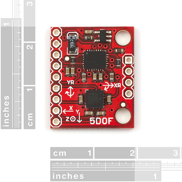
This Inertia Measurement Unit Combo Board incorporates the IDG500 dual-axis gyroscope and Analog Devices triple axis ADXL335 accelerometer in a tight footprint. The IMU board uses a standard 0.1" footprint and includes all outputs from both the IDG500 gyro and ADXL335 accelerometer ICs.
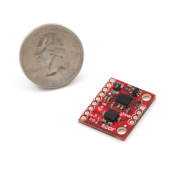
This IMU 5DOF is the latest in a long line of development boards. This latest version allows an unheard of 5 axis of sensing (Roll, Pitch, X, Y, Z) in less than 1 square inch, and under 2 grams!
By combining the IDG500 and ADXL335 sensors, the IMU board enables students and hobbyists to easily incorporate roll, pitch, and tilt measurements into their projects or robots.
Board comes fully assembled and tested. Units come as shown without headers installed. We recommend right-angle break away headers, straight pin headers, or wire up your own cable!
Having a hard time picking an IMU? Our Accelerometer, Gyro, and IMU Buying Guide might help!
Weight: 2g
- 0.75x0.9" (20x23mm)
- IMU 5DOF Schematic
- ADXL335 Datasheet
- IDG500 Datasheet
-
Resources and Applications (Inverted / reverse pendulum robots, Unmanned Aerial Vehicles, etc.):
- Reverse Pendulum Robot Project
- The ADXRS vs. the Tokin CG-16D
- Helicopter Autopilot
- Fire Marshall Bill Robot
- Wiring Example (IDG500)
Comments
Looking for answers to technical questions?
We welcome your comments and suggestions below. However, if you are looking for solutions to technical questions please see our Technical Assistance page.
Customer Reviews
No reviews yet.
Hello my friends, I have a question about the code to read the output of IMU IDG500/ADXL335. I saw the wonderful program in this page. Are there other similar code to download on the web?
Thank you
Stefano
Could you send me the schematic as an eagle file so I can inport this?
I want to build a self balancing transportation system similar to segway. I use PIC microcontroller with the IMU 5 degrees of freedom from Sparkfun to control the tilt but i have a problem in the best way to combine the readings from both gyro and accelerometer by using the PIC.. I searched on the internet and i found that the best way is to use the Kalman filter.I searched a lot to find code for Kalman filter
in PIC because i did not deal with Kalman filter before, but i did not find, all the codes are for Kalman filter in Arduino...
Please, if anyone knows how to combine the both readings by using Kalman filter in PIC>>> Please tell me
If I am not using the AZ input for the gyro, do I pull this input low?
See what I did with this 5 DOF IMU:
http://www.youtube.com/watch?v=y1dbYXfPunQ
I'm now working on version 2.0
i am new to robotics and just got started with a pic microcontroller. i am planning to build a quadcopter. i would like to know whether this combo can be used with a pic microcontroller also ( with MPLAB used for coding). also i would like to know whether this combo is is good enough for quadcopters.
Thanks in advance...
When I used the gyroscope in this IMU, I found the sensitivity 2.0mV/(deg/s) for X-/Y-OUT pins don't match the calibrated sensitivity which I found it around 0.85mV/(deg/s). Could you tell me why?
How does one achieve the 1.35V Vref and 100uA Load Drive Current? I am using the Arduino Mega microcontroller which has a 3.3V output, so by simple voltage division I am able to get the 1.35V pretty easily. However, the current is giving me issues? How should I be dealing with this?
What measurement frequency is this board optimized for?
I have just ordered this product, and it is good, what I don't understand is why not put another LDO for the accelerometer? I had a lot of trouble finding a 3V LDO just to run this thing. If we could power this sensor from a 5V supply, this product will be spot on!
the idea is good but it's not well designed
what the point of R1 and the regulator !!!
What is the "refresh rate" on the outputs?
Eagle Schematic for this?
Email us at techsupport@sparkfun.com and we can get that to you.
Hi, I still did not understand haw to power it. I Know that accelerometer and gyroscope run at 3.3V but I also know that there is a LDO!
Does it means that we can power the board with 5V?
bye
The accelerometer is basically attached to the 3.3V input, where the gyro is connected to the output of the regulator so you still need to power the board at 3.3V. I'm sure your immediate follow up questions is "Why? That doesn't make any sense." We agree and are looking into either figuring out why we did that or doing a revision of the board.
Dear sir,
The board is not working properly, the reason is because the regulator you attached to the board (in order to supply the gyro) is a 3,3v nominal It should be 3,0 v.
The gyro need 3,0 v nominal (2,7 v minimal and 3,3 v maximal) that's the reason that someone put there a regulator, in order to transform 3,3 v supply to 3,0 v to the gyro.
All the problems of nos giving a good lecture or simply not working the gyro is because of it.
A revision of the board is necesary.
What is part number for the regulator chip? I assume it is a 5VDC to 3.3VDC LDO?
I have a question about the performance of the IDG500 (and an answer to a previous post):
So, I'm reading the gyro info through an ADC on an Arduino UNO, and using the following math to convert to deg/s:
gyro_ds = (float(raw_adc)*VDD/1024 - g_offset)/g_sensitivity;
where raw_adc is the analog signal, VDD is the reference voltage of the ADC (5000mV), g_offset is the zero-offset (1350mV in spec sheet) and g_sensitivity is the sensitivity (2.0 mV/deg/s, also from specs).
That's all fine and dandy, and I'm getting readings. However, when I shake the IMU (even slighlty) the gyros indicate rotation... the gyros are picking up linear accelerations... This is throwing off my calculations for attitude.
Is this normal behavior? Has anyone experienced similar issues (and found a solution)?
Thanks
This is analog output? resolution?
I've got a REALLY old breakoutboard from SFE with the 5DOF setup with a ADXL330 and IDG300 on it. There is no longer a page for it even in Retired because it has been superseded by this page. I'm seeing different numbers when supplying a 3.3V input for the total range, when I calibrate to -1g/1g on the Z axis I'm gettin 323mv per g and not the 550mv per g I should expect. Is anyone else getting "odd" results with this board (granted mine is slightly different)?
If you are seeing numbers in the 500+ range, you might be using 5v power supply when the spec says to use 3.3v
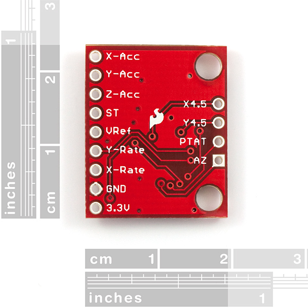
What exactly are the other 4 pins for? they are labeled but theres nowhere definitive to tell me what they do.Is there a reason everything is so vague? I do understand if I damage the board its my own fault but I would also like to maximize the potential of this board. IE measure pitch roll azimuth if at all possible. The main reason I bought the board were for the pitch roll features yet I am finding it hard to access this information easily. Some Help?
Hey, been trying to get this to work with an Arduino Uno. Has anyone been able to do that? The gyro keeps floating positive like crazy, and I can't seem to bring it back down. What equation are people using to change the arduino's reading into degrees/second??
I know price isn't everything, but I'm a little surprised. This seems to be $10 more expensive than the combined price of the breakout boards for its two component ICs. Certainly this package is more convenient if you need both, but... why is it more expensive?
Point taken. Sometimes costs are figured on early builds. If an early build is expensive for us, that happens. Fixed now.
To get it to fit a breadboard (in the middle of course) I had to bend the pins I soldered. That was kinda silly...
Just got my 5DOF and noticed the same thing. While the two rows of header vias are on 0.1 spacing they are not in alignment with each other on a 0.1 grid spacing (horizontally or vertically) making it difficult to use with a solderless, drilled breadboard or proto shield using pin headers. You can see this in the product pictures above if you look carefully. Now that they are out of stock, maybe SF will adjust the layout ever so slightly for the next PCB run.
Hi Guys. Here's the deal, we designed this board so that the most commonly used headers are all along one side. The extra 4 pins are for advanced features, and should only be needed in certain situations. You will likely be happy just using the long row of headers. In the case that you need access to the additional 4 pins, you might want to use jumper wires attached from the top to run out to your breadboard.
Here is another tutorial with source code of a simplified Kalman filter on Arduino:
http://www.starlino.com/imu_kalman_arduino.html
Here is a great tutorial using this one with Arduino and Processing:
http://www.glacialwanderer.com/hobbyrobotics/?p=261
Spanish version here:
http://blog.bricogeek.com/noticias/arduino/sistema-de-medicion-inercial-con-arduino-y-processing/
i think SFE should share codes for arduino about imu5dof.
for measuring x-y angles.
because we cant use it without kalman filter knowledge :-(
This is probably mentioned somewhere in one of the links given above in the product description,
http://www.rotomotion.com/downloads/tilt.c
http://www.rotomotion.com/downloads/tilt.h
it seems to work fairly well for me
Hi all,
I use pic microcontroller to take the readings from IMU and monitor the filtered reading (by using a complementary filter) on LCD.. But when i turned the power supply ON, the reading of gyro at static or zero case was 604 then when i turned the power OFF then ON again the reading was 617!!!!! so i want to know why the zero reading of gyro varied like this it should be constant right????
PLEASE EXPLAIN THIS FOR ME.
Thanks..